George
The buffer version sounds great after burn-in. I will be going in the other direction. While I was building my preamp, forgot that my amp needs between 1.7and 2 volt rms for full output. With the amp wired as a “buffer” and a dvd player playing cd, the signal max out at 1.456volts peak. I hope my preamp with gain sound as good as yours.
The buffer version sounds great after burn-in. I will be going in the other direction. While I was building my preamp, forgot that my amp needs between 1.7and 2 volt rms for full output. With the amp wired as a “buffer” and a dvd player playing cd, the signal max out at 1.456volts peak. I hope my preamp with gain sound as good as yours.
Wait till you try the version with gain
The gain version has better harmonics and less electronic sound. At least how I built them.
I did add a set of snubbers to the 1K on board caps. Iam going to move them to the offboard 6800 ufd caps to see if this is adding an edge somehow.
This one has a pair of 100 ufd caps right on the supply pins, less than 1 cm from the cap body to the pins on all four leads. The circuit with gain has a lot more lead length, the caps were placed after most of the resistors and it was impossible to snug them up underneath the chip. This alone I figured would make the buffer one better sounding.
Good luck with yours!
George
Re: Nother version
George, if I understand you correctly, you are doing what I told you not to do
You should not use a shunt for feedback, you must use a resistor with a value around what's recommended by AD on the datasheet.
Please break that shunt and put a resistor there.
562R is recommended, but something around this value is fine. Use 560R if you have, or else use those 480R, but never a shunt.
IrfanView is free and you can surely shrink those pics, no problem.
If you want, send me the files, I'll post them.
Panelhead said:I built one this week leaving off the 330 ohm resistor running from the inverting input to ground. a buffer so to speak. It is working fine.
Previous one used 480 ohm resistors for feedback and for this shunt.
George, if I understand you correctly, you are doing what I told you not to do
You should not use a shunt for feedback, you must use a resistor with a value around what's recommended by AD on the datasheet.
Please break that shunt and put a resistor there.
562R is recommended, but something around this value is fine. Use 560R if you have, or else use those 480R, but never a shunt.
Panelhead said:I would post pics, but lack software to shrink them down from 2 meg to a postable size.
IrfanView is free and you can surely shrink those pics, no problem.
If you want, send me the files, I'll post them.
I do it!
I will take a couple more of the board. Then send, the unmounted pics were not very clear.
BTW, my description is not very good. I am using a 618 ohm resistor for the feedback, and it is the only thing tied to the inverting input. I picked up some 533 ohm to use here, but left them at home and did not have them when building this board.
George
George
If you have two email account,you can use google's picasa2 photo software. It very easy to use. Take your picture picasa will automaticlly load them to the picasa program,then you use the email button and sent the pictures to your other email account,the file size is automaticlly reduced.
If you have two email account,you can use google's picasa2 photo software. It very easy to use. Take your picture picasa will automaticlly load them to the picasa program,then you use the email button and sent the pictures to your other email account,the file size is automaticlly reduced.
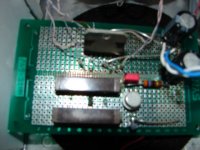
Bottom shot of board
This is where all the passives live. The resistors, two 100 ufd caps, and a couple films for the nulling circuit.
The snubbers have been moved to the 6800 ufd caps mounted in the chassis. And those ceramic caps discarded and replaced with a proper polystrene.
This is where all the passives live. The resistors, two 100 ufd caps, and a couple films for the nulling circuit.
The snubbers have been moved to the 6800 ufd caps mounted in the chassis. And those ceramic caps discarded and replaced with a proper polystrene.
Attachments

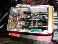
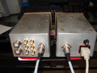
Back of divider
The pair of 6800 ufd Panasonic FM caps now have snubbers installed. They are in the upper left, next to the power input.
The PEC mono pots seem to track really well.
One of my latest finds, a real sweet Centralab 2 pole, 5 position shorting switch. Has steatite wafers and silver contacts. They made nice switches 50 years ago.
Attachments
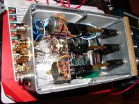
Last, the power supply
It hard to see, there are discrete bridges with 20 A, 100 V, schotkies, filter caps, 317/337 regs, film caps, 1 mH chokes, 1000 ufd caps bypassed with film caps, and the 10 mH chokes. This is the C-L-C-L filter feeding the preamp.
There is a RC filter on the input to the transformer, never can have too much filtration.
It has powered the last few linestages used with low voltage, dual rail supplies. It is real quiet.
The AD815 is a real nice chip. It has easily bettered all the 8 pins opamp circuit I have tried. It even beats my discrete current sourced fet, with bipolar cascodes.
Guess this current feedback thing has real merit. Thanks for the help with circuit help and posting these pics.
George
Attachments
George
Do you have picture for the outside of your preamp?
Where did you get those shaft coupling?
Do you have picture for the outside of your preamp?
Where did you get those shaft coupling?
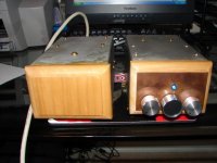
Re: Big Brother
Laugh? 😕
That looks cool, man.
Panelhead said:Do not laugh at the boxes used. They are cast from a solid billit of aluminum.
Laugh? 😕
That looks cool, man.
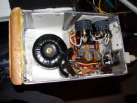
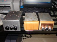
Gut shot
The AD815 circuit is in the box on the right. The circuits are on identical boards, a modular approach. It would take 30 minutes to swap circuit from box to the other.
The big box has a discrete fet, current sourced, with BJT cascodes on both circuit. Also a pair of 55,000 ufd four pole Jensen caps, S & B output transformers, and the box is lined with mumetal.
The output iron is under a mumetal sheet, under the input transformers.
BTW, the driveshafts were sourced from Tanner Electronics in Dallas. I have not seen any out there in the last year of so. Maybe they moved over to BG.
George
Attachments

Panelhead, they look fine. I hope that when my time comes, I'll be able to produce something like that. 🙂
Carlos, I know you may view this as a stupid question but for a noob like me, I have no other choice but to ask. I just received my AD815 chips and hope to embark on this after finishing up my LM4780. My question is whether this design uses 1 chip for both channels as I see in the pictures of your built up pre or it actually uses only 1 side of the chip to power one channel, thus requiring 2 chips? 😕
Carlos, I know you may view this as a stupid question but for a noob like me, I have no other choice but to ask. I just received my AD815 chips and hope to embark on this after finishing up my LM4780. My question is whether this design uses 1 chip for both channels as I see in the pictures of your built up pre or it actually uses only 1 side of the chip to power one channel, thus requiring 2 chips? 😕
safetyman said:Carlos, I know you may view this as a stupid question but for a noob like me, I have no other choice but to ask. I just received my AD815 chips and hope to embark on this after finishing up my LM4780. My question is whether this design uses 1 chip for both channels as I see in the pictures of your built up pre or it actually uses only 1 side of the chip to power one channel, thus requiring 2 chips? 😕
I use a single chip for two channels.
carlosfm said:
I use a single chip for two channels.
Carlos, thanks for the reply. I'll try to figure the schematic out. It's not easy for me but I don't wanna give up if you are willing to help me. BTW, can this pre be built using only the first 2 sections of your schematic and omitting the DC-offset null circuit?
Hi Shehzad
you can omit the DC nulling but then you have to use the caps on the output (not bad sounding just use very good quality, a Wima MKP will work just fine.)
do not change anything else on the circuit, specially the powersupply, I did and the results weren't as i hoped so keep to Carlos's circuit
you can omit the DC nulling but then you have to use the caps on the output (not bad sounding just use very good quality, a Wima MKP will work just fine.)
do not change anything else on the circuit, specially the powersupply, I did and the results weren't as i hoped so keep to Carlos's circuit
- Status
- Not open for further replies.
- Home
- Amplifiers
- Chip Amps
- (re)searching for a better preamp