Hello, just wanted to ask just how hot the SMD AD815 is getting for the ones that has build with it?
I've a layout on eagle that is 2x2 inches with the "heatsink" layer on both sides (2 layer board connected with many vias) and the "heatsink" takes up about 75% of that.
Would that be enough you think?
Thanks
I've a layout on eagle that is 2x2 inches with the "heatsink" layer on both sides (2 layer board connected with many vias) and the "heatsink" takes up about 75% of that.
Would that be enough you think?
Thanks
Tobias, the SMD version gets quite warm, but as long as you provide some "heatsinking" (your plan is fine), no problem.
Hey, my pre is working for almost two years, and sometimes it's powered on for days.
The non-SMD chip doesn't even get warm, I suspect that it's metal tab is enough heatsinking. 😀
Hey, my pre is working for almost two years, and sometimes it's powered on for days.
The non-SMD chip doesn't even get warm, I suspect that it's metal tab is enough heatsinking. 😀
hi Tobias
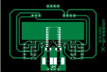
I have build a few SMD versions now and the one thing that i have learned from this is that you have to have the heatsink pad 90deg from the heat tabs. if you sart them of at an angle they aren't as effective. it runs 30 % cooler this way.
be warned it does get very hot but after some running in it settles but the heat it generates is far below the max specification of the chip
look at my example. you can make the pad bigger than this. another idea i haven't tried yet, but i am sure it will work. is to solder some think copper to the heat tabs.
Attachments
hello Carlos and Rudi
okey, i see in your picture Rudi that i have bigger heat-plane so it should work.
It's somethink like this with the psu-pcb ontop of the other and the pins on the elcos after the regs are going straight thru down to the AD815.
http://www.ettnet.se/~tobias/diy/ad815/smd/
Edit: Oh, and yes I got some ideas from your board Rudi 🙂 kinda hard also to do it in another way with this chip.
Hello folks,
I'm trying to cobble together this circuit using the SIP version on veroboard.
I have something called vero microboard, which has pads and power rails on one side and a ground plane on the other.
Would the ground plane cause a problem here, or could I use it to my advantage?
Or should I just stick to standard stripboard?
I know this is not ideal, but I can't make my own boards. Using the vero means soldering the back legs of the chip to the board and clipping the front legs and 'air-wiring' them because the pin spacings aren't the standard 0.1 pitch
Easy enough
Try bending the pins to fit your board. I clipped off the unused 3 from one end and 4 from the other. Then bent the used 8 pins to fit my standard boards.
Using two rows of the latest has the +inpuit L, output L, + rail, output R, and + input R on the front side. The -input L, ground, - rail, ground, and -input R in the back. This layout worked the best for my buffer, all the input and outputs are on the same side of the chip. This allows for much cleaner connections.
I need to finish something and then build a better supply for mine. The supply I use now is very clean, but very high impedance. I suspect it is limiting current to the chip at loud levels.
George
float said:Hello folks,
I'm trying to cobble together this circuit using the SIP version on veroboard.
I have something called vero microboard, which has pads and power rails on one side and a ground plane on the other.
Would the ground plane cause a problem here, or could I use it to my advantage?
Or should I just stick to standard stripboard?
I know this is not ideal, but I can't make my own boards. Using the vero means soldering the back legs of the chip to the board and clipping the front legs and 'air-wiring' them because the pin spacings aren't the standard 0.1 pitch
Try bending the pins to fit your board. I clipped off the unused 3 from one end and 4 from the other. Then bent the used 8 pins to fit my standard boards.
Using two rows of the latest has the +inpuit L, output L, + rail, output R, and + input R on the front side. The -input L, ground, - rail, ground, and -input R in the back. This layout worked the best for my buffer, all the input and outputs are on the same side of the chip. This allows for much cleaner connections.
I need to finish something and then build a better supply for mine. The supply I use now is very clean, but very high impedance. I suspect it is limiting current to the chip at loud levels.
George
Re: Some considerations for the R&D team
My dear friend Carlos........ I have tried it......it works great....sorry....incredible.. 😀
Now help me understand what happened here. I know I can go through 100000000000 threads with 99999999999 contradicting explanation
can you explain to me. very simply how this works and what is it doing. then i also need to know if the order of the cap and the resistor makes a difference.
one small artifact that i got. I am hearing a clicking noise (comming from the electric fence - yes dudes this is africa ) on my system now.
carlosfm said:
I have calculated (for another project) snubber values to use after the LM317/337 regs.
These are 0.47R + 22uF.
I didn't try it here, but for the most adventurous (!) that are using LM317/337 regs on this pre, try it.
My dear friend Carlos........ I have tried it......it works great....sorry....incredible.. 😀
Now help me understand what happened here. I know I can go through 100000000000 threads with 99999999999 contradicting explanation
can you explain to me. very simply how this works and what is it doing. then i also need to know if the order of the cap and the resistor makes a difference.
one small artifact that i got. I am hearing a clicking noise (comming from the electric fence - yes dudes this is africa
) on my system now.Re: Re: Some considerations for the R&D team
rudi, you have an electric fence? 😕 Man, you must be one of those rich billionaires of Johannesburg. 😀
It was really nice talking to you. I hope you enjoyed it as much as I did.
rudi said:
one small artifact that i got. I am hearing a clicking noise (comming from the electric fence - yes dudes this is africa
rudi, you have an electric fence? 😕 Man, you must be one of those rich billionaires of Johannesburg. 😀
It was really nice talking to you. I hope you enjoyed it as much as I did.
Re: Re: Re: Some considerations for the R&D team
well I wish i was one. almost everyone in JHB have electric fencing and 10ft walls. (we decorate our walls to impress our neighbours not our houses )
it was good to finally chat. 😉
safetyman said:
rudi, you have an electric fence? 😕 Man, you must be one of those rich billionaires of Johannesburg. 😀
It was really nice talking to you. I hope you enjoyed it as much as I did.
well I wish i was one. almost everyone in JHB have electric fencing and 10ft walls. (we decorate our walls to impress our neighbours not our houses
)it was good to finally chat. 😉
float said:Hello folks,
I'm trying to cobble together this circuit using the SIP version on veroboard.
I have something called vero microboard, which has pads and power rails on one side and a ground plane on the other.
Would the ground plane cause a problem here, or could I use it to my advantage?
Or should I just stick to standard stripboard?
I know this is not ideal, but I can't make my own boards. Using the vero means soldering the back legs of the chip to the board and clipping the front legs and 'air-wiring' them because the pin spacings aren't the standard 0.1 pitch
You should read the application note, I think it says something about keeping ground trace a certain distant way from signal traces.
The sip package will fit on a veroboard with alittle bending of pins. Place the pins the are not (NC) first then bent the NC pin to the nearest hole.
jaudio said:
You should read the application note, I think it says something about keeping ground trace a certain distant way from signal traces.
The sip package will fit on a veroboard with alittle bending of pins. Place the pins the are not (NC) first then bent the NC pin to the nearest hole.
well this is true for applications that require Mhz bandwidth but not for audio.
Hi Rudi,
So you have tried subberizing the board (single regualation) i built and this improves the sound?
Where abouts are you are you putting the subber in the circuit?
Now this fun interesting.
Phil
So you have tried subberizing the board (single regualation) i built and this improves the sound?
Where abouts are you are you putting the subber in the circuit?
Now this fun interesting.
Phil
Hi Phil
I have done it on the double regulation, I will try it on single regulation tomorrow.
you should also try it, it goes directly after the LM3xx
rail - resistor - cap - ground. in that order.
I have seen people do it the other way round for negative ????????????? I am as confused as hell.
here is the interresting bit. when you have your speakers out of phase you get a sound that kinda fills the room with zero focussing. (try it) it is almost like a surround effect.
well with this setup it felt like that but with focussing..... go figure..I am baffled with this. the sound stage is huge and very natural 😀 I actually had to check if i didn't do something funny at the back of the amp. but everything is still in order.
I have done it on the double regulation, I will try it on single regulation tomorrow.
you should also try it, it goes directly after the LM3xx
rail - resistor - cap - ground. in that order.
I have seen people do it the other way round for negative ?????????????
I am as confused as hell.here is the interresting bit. when you have your speakers out of phase you get a sound that kinda fills the room with zero focussing. (try it) it is almost like a surround effect.
well with this setup it felt like that but with focussing..... go figure..I am baffled with this. the sound stage is huge and very natural 😀 I actually had to check if i didn't do something funny at the back of the amp. but everything is still in order.
Re: Re: Some considerations for the R&D team
You are just reporting to me (thanks for that) that it works, that I know what I'm after and I know how and what to calculate for the snubbers.
I won't say anything more about snubbers, I'm a peaceful man.
rudi said:My dear friend Carlos........ I have tried it......it works great....sorry....incredible.. 😀
Now help me understand what happened here. I know I can go through 100000000000 threads with 99999999999 contradicting explanation
You are just reporting to me (thanks for that) that it works, that I know what I'm after and I know how and what to calculate for the snubbers.
I won't say anything more about snubbers, I'm a peaceful man.
rudi said:
the preamp have about 12 hours on it now and it is improving by the hour. it is really sounding awesome. but i would like to have another 30 on it before i make my final judgement
Hi Rudi
It has been more than 30 hours,how does the preamp sound?
Re: Re: Re: Some considerations for the R&D team
mmmmph .... and i thought you were a friend 😡
DUDE......... hey........explanation please 😕
Sweeeeet...very sweeet.
 lalala...lala la
carlosfm said:
You are just reporting to me (thanks for that) that it works, that I know what I'm after and I know how and what to calculate for the snubbers.
I won't say anything more about snubbers, I'm a peaceful man.
mmmmph .... and i thought you were a friend 😡
DUDE......... hey........explanation please 😕
jaudio said:
Hi Rudi
It has been more than 30 hours,how does the preamp sound?
Sweeeeet...very sweeet. lalala...lala laRe: Re: Re: Re: Some considerations for the R&D team
Hey, I am a friend, but I'm not willing to discuss all this anymore, it's more problems for granted.
I've been there, done that, it isn't worth it.
You have the values that I recommend for the LM317/337 regs, it works, be happy with this. Use them.
I'm just going to tell you the obvious (or should be by now): you've lowered the (high) impedance of your PSU, where it matters the most.
PS: you should be using a ferrite ring around the mains cable near the trafo (I always do), probably it solves your problem with that electric fence.
And twist the wires.
rudi said:mmmmph .... and i thought you were a friend 😡
DUDE......... hey........explanation please 😕
Hey, I am a friend, but I'm not willing to discuss all this anymore, it's more problems for granted.
I've been there, done that, it isn't worth it.
You have the values that I recommend for the LM317/337 regs, it works, be happy with this. Use them.
I'm just going to tell you the obvious (or should be by now): you've lowered the (high) impedance of your PSU, where it matters the most.
PS: you should be using a ferrite ring around the mains cable near the trafo (I always do), probably it solves your problem with that electric fence.
And twist the wires.
jaudio said:Ok
that is the Walter Jung preamp with double regulation and snubbers?
thats the one. What i really like about it is the sweetness that you get from the OPA627 ( I am not using the suggested AD823 ) but still all the drive from the AD815 and all its other fantastic atributes
you can tailer it to sound just the way you want it
rudi said:you can tailer it to sound just the way you want it
Is that good?
That's what I wanted to avoid...
- Status
- Not open for further replies.
- Home
- Amplifiers
- Chip Amps
- (re)searching for a better preamp