And yet they both work with the PMD100.BCK reclocking may be needed for PCM1702 and PCM1704 as they use BCK for latching dac output.
If I would want to compare the phase noise of two flip-flops at work, I guess I would connect them as dividers by two, apply a clean clock from a crystal oscillator and a clean power supply and look at the output signals (sidebands and floor) with a spectrum analyser with a low phase noise. A phase noise measurement system is better, but not available at the place where I work.

Yes I know, since I use PMD100 with PCM1702. I haven't tested how much deglitching period can be varied with PCM1702.And yet they both work with the PMD100.
A follow up on the breadboard plug-n-play test jig I set up.
Earlier I showed photos of a Philips 74HC74 (ic manuf. sometime in 2004)
Philips 74HC74:
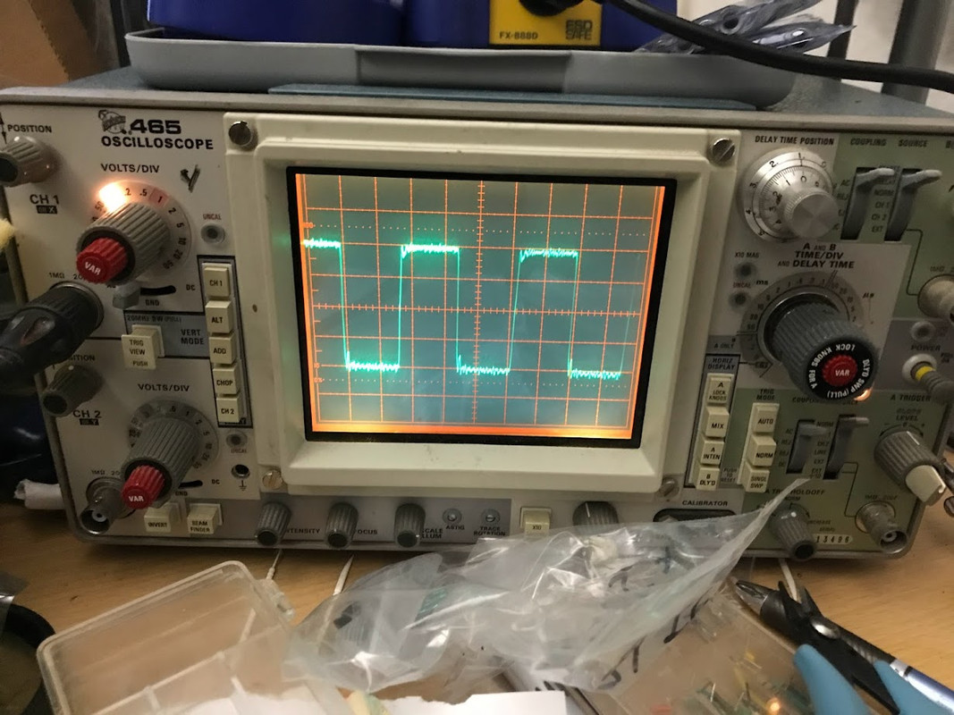
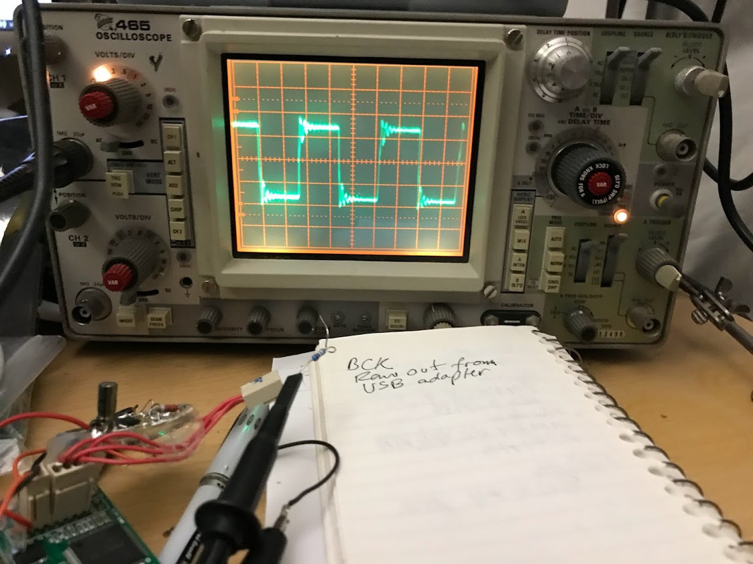
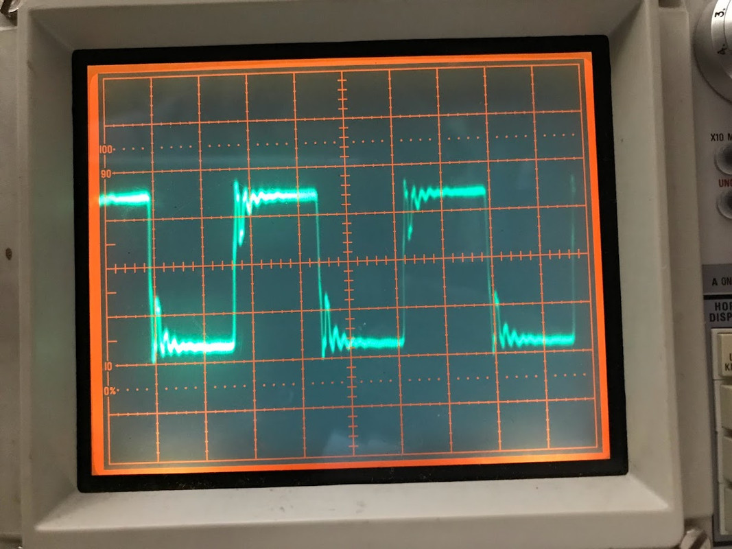
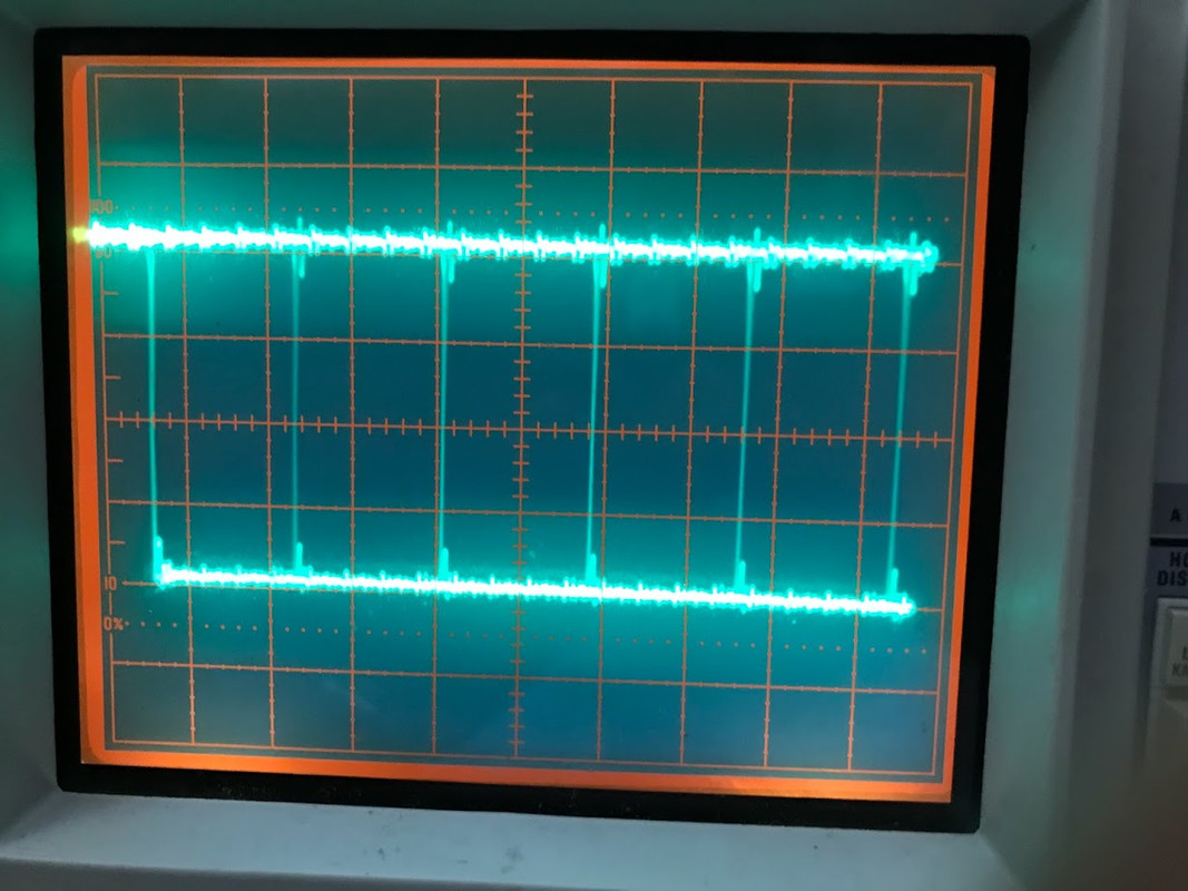
Below are from the same test jig. Nothing changed but the 74 F-F ic itself. Input (D) is BCK from USB adapter.
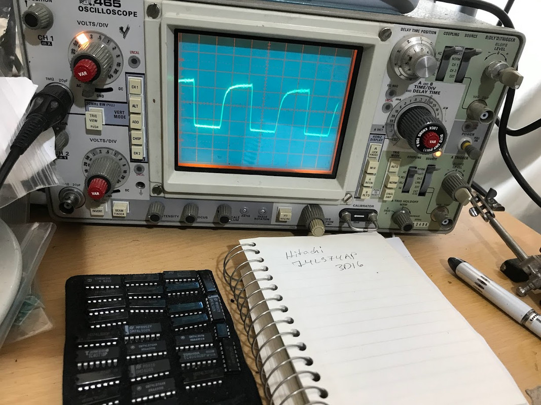
Early 90's vintage Hitachi 74LS74AP:
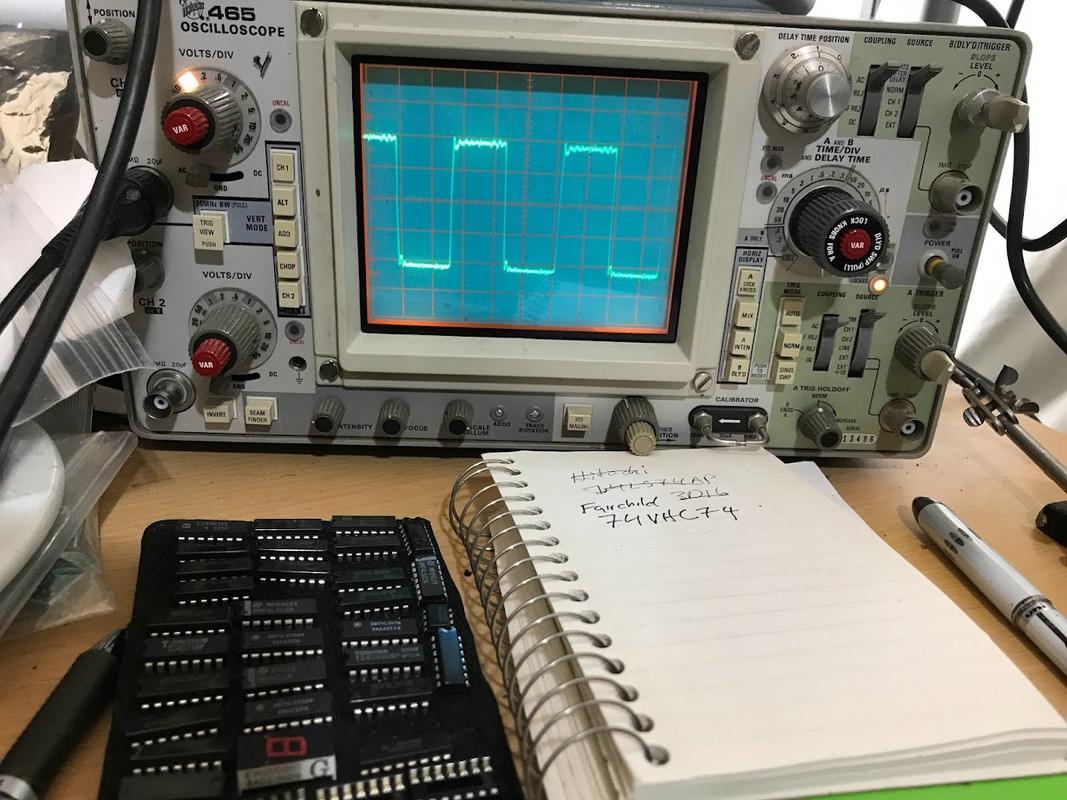
Fairchild 74VHC74 (date code: shown Feb 2005)
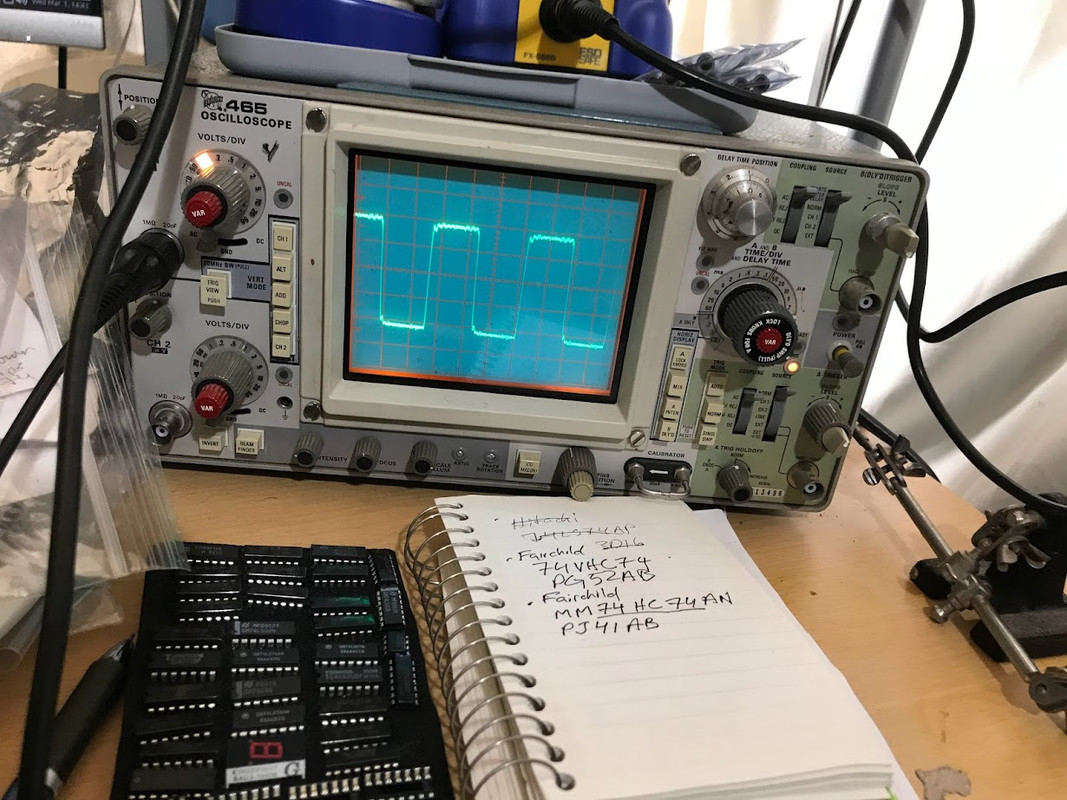
Fairchild 74HC74 (date code: shown Jan 2004)
Earlier I showed photos of a Philips 74HC74 (ic manuf. sometime in 2004)
Philips 74HC74:
Below are from the same test jig. Nothing changed but the 74 F-F ic itself. Input (D) is BCK from USB adapter.
Early 90's vintage Hitachi 74LS74AP:
Fairchild 74VHC74 (date code: shown Feb 2005)
Fairchild 74HC74 (date code: shown Jan 2004)
Last edited:
So why reclock BCLK when it isn't running at conversion ?
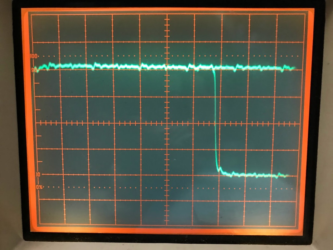
Maybe because of this --- raw BCK coming out of USB adapter; no 74HC re-clock ic. Note the ringing spike.
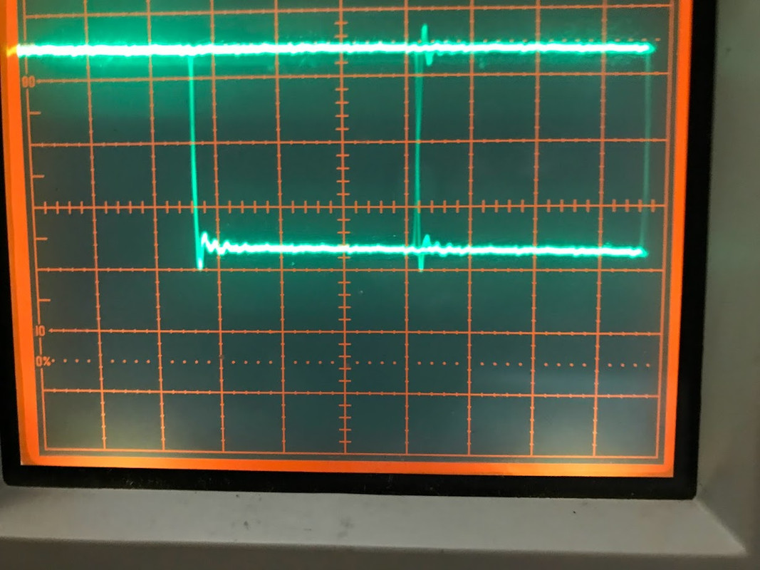
Adding a series 49R does clean things up a bit, however:
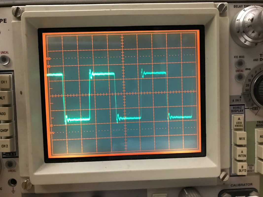
All that said, the no reclock signal does look overall cleaner AFTER that initial ring "blip" (see my prev. photos, testing various 74's )
That is not relevant to the specific case of the PCM1702/4 and the PMD100 and the notion that there is any value in reclocking BCLK. Seems to me like pointless noise generation. One could at least stop the reclocking when BCLK is not running.
Last edited:
So why did you confuse this thread with that distraction? Try to stay on topic and keep things SIMPLE as the title/subject suggests.That is not relevant to the specific case of the PCM1702/4 and the PMD100 and the notion that there is any value in reclocking BCLK.
For example, are 54 (Military) grades superior? Or are there certain manufs of logic devices that offer better performance (Potato)? Or vintage vs new logic chips. Or tweaking the input or output lines or voltage rails.
The 54 ICs are the exact same chips in packages that are more suitable for extreme temperatures (and are sometimes better protected against moisture).
Have you read the PCM1702 & PMD100 datasheets? From PMD100 datasheet: BCK is halted until LE (WCKO) changes state. From PCM1702 datasheet: the change in the output of the DAC occurs at a rising edge of the 4th clock of the BCK (CLOCK) after the falling edge of LE.So why reclock BCLK when it isn't running at conversion ?
Let's move onto reclocking vs no-reclocking the DATA line....
Same breadboard set up as before.
Reclocker IC: Fairchild 74HC74 (manuf date: Jan 2004)
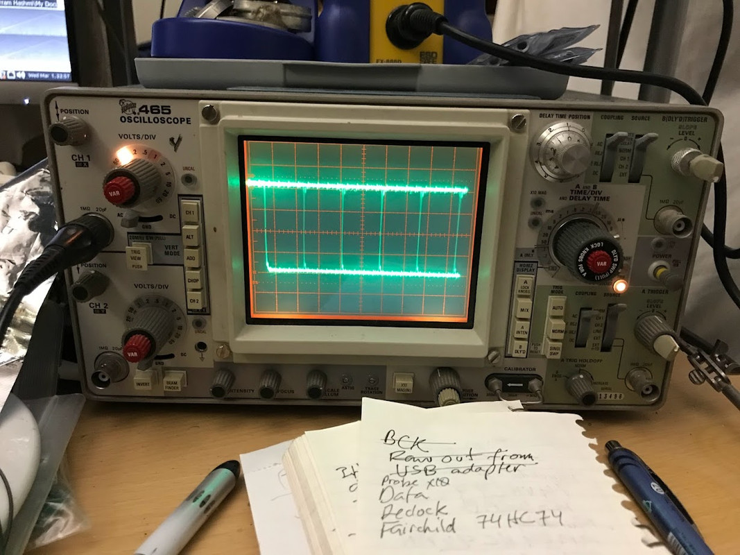
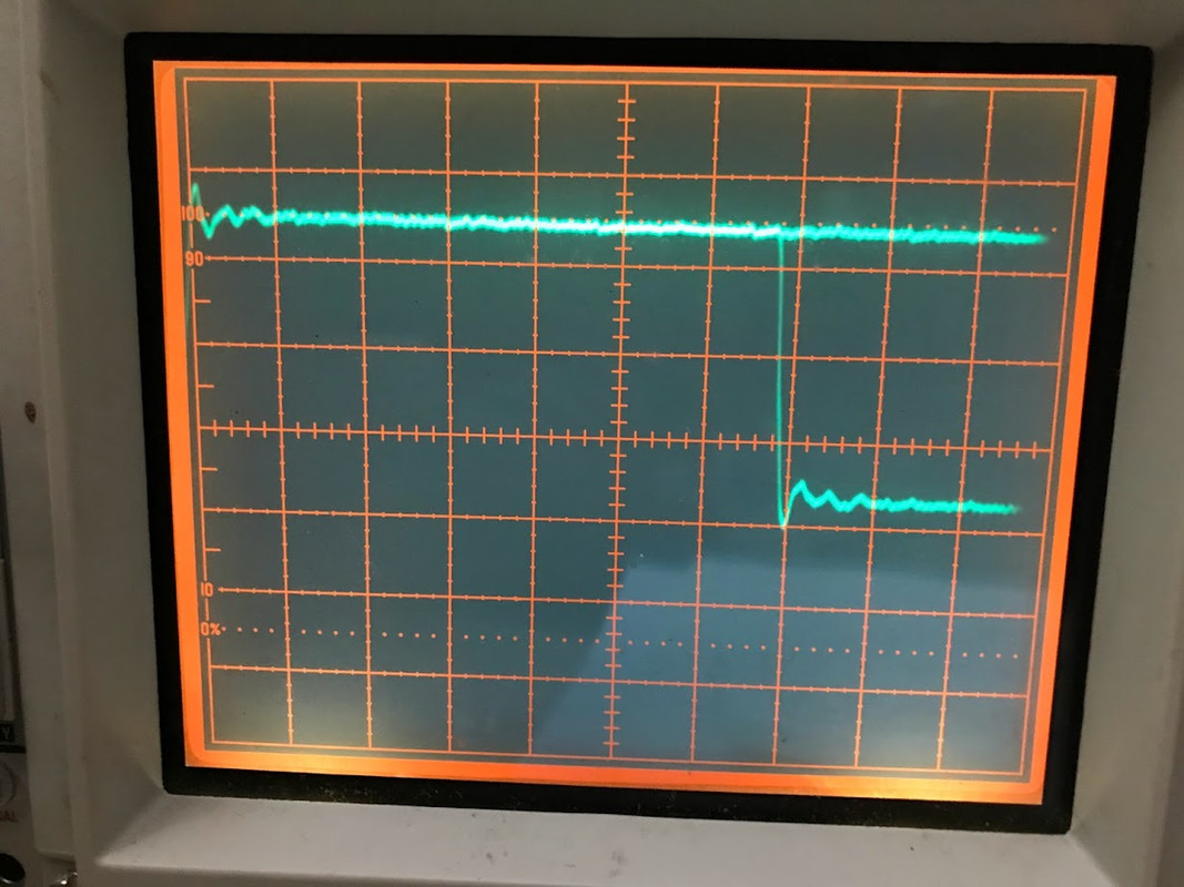
No reclock -- DATA straight out of USB adapter:
Some of the "old boys" who work with analog 'scopes and bread boards proclaim benefits of hands-on tweaking: watching very tiny pattern changes as breadboard components are added/subtracted. I concur. E.g., adding film caps to rails made for very tiny but noticeable changes in waveforms that may have been neglected otherwise.
Same breadboard set up as before.
Reclocker IC: Fairchild 74HC74 (manuf date: Jan 2004)
No reclock -- DATA straight out of USB adapter:
Some of the "old boys" who work with analog 'scopes and bread boards proclaim benefits of hands-on tweaking: watching very tiny pattern changes as breadboard components are added/subtracted. I concur. E.g., adding film caps to rails made for very tiny but noticeable changes in waveforms that may have been neglected otherwise.
I find page 7 of the PCM1702 datasheet and page 8 of the PMD100 particularly relevant.Have you read the PCM1702 & PMD100 datasheets?
Nice pictures and all but what do you think reclocking gets you? There well regarded dacs that do not reclock and there are very expensive broadcast devices that do using the same df/dac chipset. Have to say once you get to the level of romanticising different generations of TTL device ............Let's move onto reclocking vs no-reclocking the DATA line....
Earlier, I noted the relevance of eye diagrams to jitter.
In the following short video tutorial from TI, eye patterns and significance to TOTAL JITTER are mentioned.
In the following short video tutorial from TI, eye patterns and significance to TOTAL JITTER are mentioned.
Eye diagram jitter analysis is far too coarse for use with dacs. Eye diagrams are more about being able to recover bit information without data loss. Dac jitter is much more sensitive because much less jitter and or close-in phase noise than is visible on normal scopes in an eye pattern already distorts and or adds noise to dac audio output.
Last edited:
Eye diagram is good, but you can imagine its uselessness if you compare the period of signals used in audio with acceptable jitter.eye diagrams to jitter.
- Home
- Source & Line
- Digital Line Level
- Re-clocking I2S (simple version)