Hi diyrayk
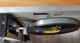
I have just modified my very old Rabco SL8 with your help on this site. Everything works fine with the optical reading, it's absolutely great!
Thank you very much for posting this step by step manual.
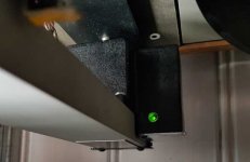
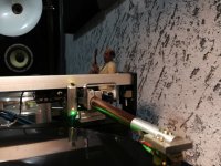
I even spent a green led for transportmotor, so i can see when he's in action.
Greetings from Switzerland, nero52
I have just modified my very old Rabco SL8 with your help on this site. Everything works fine with the optical reading, it's absolutely great!
Thank you very much for posting this step by step manual.
I even spent a green led for transportmotor, so i can see when he's in action.
Greetings from Switzerland, nero52
Glad to see another happy user of this mod. Do you have any more photos of your construction details? I like to think that the green led indicator was necessary because the motor was now running too quiet to hear, or is that vanity on my part? 🙄
Ray K
Ray K
Hi diyrayk
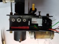
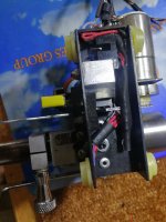
there are only two more photos. The green led indicator is just for my fun, to see that the motor is working. i have never heard the motor, but i spent hours in front of my rabco - hoping it works.
i couldn't adjust the two contactwires anymore and instead of them i took two small pieces of guitar strings. that worked for two month...
now i'm very happy after the photosensor upgrade, but i spent some hours to make it. every minute is worth it!!!
Attachments
Hi Ray thank you for your great posting, I had modified my Rabco SL8E working very good. Motor run very quietly, visually not possible see the carriage moment. I am very happy, this arm will work another 50 years trouble free. I would like add led for carriage motor moment like Nero52. I had try to add led before R1 resistor (Q1 collector), working but I feel motor get too slow! Pls advice where I can connect led. Tks Rajkumar
Last edited:

Rajkumar_
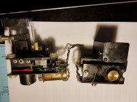
i took the 5V (Power Supply) direct from my Thorens TD 125 with a step down Module. Make sure, that the Voltage is correct after modifying with the Led, otherwise the transportmotor is too slow.
I mounted all the electronic parts onto a little print and put it inside the battery housing.
Best regards
Richi, nero52
Attachments
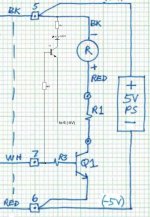
Hi nero52, thanks for your answer, so I need 1k & 4.7k what is number of transistor T1. Rajkumar
Hi Rajkumar_
you can use any of them - no problem. Voltage is 5V and the current less than 5mA. I used a BC 107 (had this in stock).
Best regards
Richi
you can use any of them - no problem. Voltage is 5V and the current less than 5mA. I used a BC 107 (had this in stock).
Best regards
Richi
Hello after photoelectric servo modification on my Rabco SL8E with led (same nero52) I have notice led turn on & off very few seconds, it’s correct.? Or led continuously turned on? Thanks Rajkumar
The LED circuit itself is probably working correctly. The ideal is for the motor to operate continuously, and speed up or slow down as the groove pitch varies. You can verify this most easily by monitoring motor voltage directly with an analog voltmeter. With a theoretically constant groove pitch, the motor voltage will also be constant. Groove pitch in the real world is not constant and records are also off-center to some extent, so motor voltage isn't constant but varies up and down with each revolution. LED's like to be either on or off. My guess is that the LED circuit is biased somewhere in the middle of the motor's actual operating voltage range and is turning on and off as the motor swings within that zone. The LED turn-on point could be manipulated by selecting the gain of the added transistor and the value of the added 4K7 resistor.
I deliberately did not include an LED indicator on my arm partly out of laziness but more out of the philosophy that, if I can't hear the effects of the servo in action, I don't want any visual cues that it's operating. I leave my test equipment connected for as long as I need to see what the servo is doing while setting it up but once that's done I prefer to fly/listen 'blindfolded'.
Ray K
Rayk absolutely you correct, I have check many LP's many of then off center this is the reason led light (motor) turn on/off, one of the my LP I found correct center than led turn on continuously. Now I have cleared my doubt. I have installed 2 led red & green. Green for carriage and red for lifting. Everything working perfectly. I have post some pictures. Tks lot Rajkumar.
Attachments
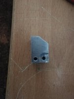

What a treasure trove of information! I am about to do this retrofit on a set up inherited from my father. I have reviewed the step by step and I am eager to replace the brass mounting block with something that is easier to fabricate. I am thinking delrin/acetal bar. It is eminently machinable (by hand). Also, it will not corrode or conduct current. Anything I am missing on the brass that should make me stick with it? Also, what is the purpose of the particular profile of the mounting block vs. a cube? Thanks for all that you are doing to keep these alive.
Hi Regarding profile of 1st image, there are 2 photo sensor will mounted those hole, on the top (profile) 1st sensor for carriage moving and 2nd sensor without profile for end record for lifting. Both sensor should not same inline, this is the reason have profile for 1st start earlier for carriage moving, 1nd sensor later for end record lifting. I hope you understand. This profile depth based on actual requirement.
Got it. This re-creates the offset that the "whiskers" have. Thanks. Anywhere I can source the block fabricated for this purpose? Does it have to be brass?
The block does not have to be brass. It can be anything that can be drilled and tapped for the mounting hardware used. I only used brass because it is easy to machine and I had a conveniently sized piece in my ‘junk’ box. The profile is unimportant other than to hold the sensors in position and be clear of the drive chain. I put a bevel on it only because I didn’t want to trim or cut away any of the foam gripper pad.
Ray K
Ray K
Thanks, Ray. I guess I will give the delrin a try then. I have some experience with it in repairing antique wooden clock movements. Btw, you and others here may be interested to know that the BOM for this has become challenging to source. I had to go to 3 different vendors to complete it. Another symptom of the pandemic-induced supply chain. The vendors were Digi-key, VTTI (for the sensors), and Mousers. I hesitate to share the specifics of the availability since it is so volatile.
John J
John J
Please share your sources to fulfill the required parts. It would be a great help.
Regards
David
Regards
David
Glad to be of help. I am not an EE and new to this hobby so, my work should be checked. Here is what I found in trying to source the BOM:
Hope this helps.
Happy New Year
- The EE-SH3 optical sensor has been discontinued. I was able to source it from TTI. I have not received my order so cannot verify the match. They report as discontinued with 16 on hand. OMRON list the EE-SH3 as a discontinued product and recommend the EE-SX1088 as a replacement. OMRON
- Several YAGEO resistors are on backlog from Digi-key: 4.75K ohm, 162 ohm, 100 ohm. Mouser had the 4.75K on hand as well as what appear to be suitable replacements from KOA Speer. P/N#s:
- MF 1/4 DC 1000F
- MF 1/4DC 1620F
Hope this helps.
Happy New Year
- Home
- Source & Line
- Analogue Source
- Rabco SL8E Photoelectric Servo Control Retrofit