Andrew never asked you to insert 10 ohm resistors in random places. Neither did I. Why not try thinking, instead of poking fun at people trying to help you?
I've gone through the thread. Could you please point out where he is poking fun at people? I can't find it.
j
..............As in having smaller storage caps on each channel which center point is each channels speaker ground with a 10 ohm resistor between it and signal ground and then three leads per channel to the main psu, is this what your trying to say ?
If yes, then that for sure hum loudly as signal and speaker ground shares the same wires.
................-- but this just seems plain wrong, but it sounds on AndrewT like that is the right way.
But to me is just seems plain wrong.
....................and i'll continue to recommend it to beginners that come to me for help no matter what ppl say.
The implication is that his description is one being proposed by Andrew T. And that Andrew T. as well as other ppl (people/Members) are not worth listening to............point out where he is poking fun at people?.......................
Inserting a 10ohm resistor and then questioning whether the resultant circuit is correct, with the clear implication that it was not, despite the fact that the resistor was his idea. Intead of addressing the points raised, he chose instead to put up a clearly ridiculous circuit while implying that was what Andrew had suggested. I call that poking fun. Perhaps I have misunderstood his motives - maybe he is just hopelessly confused?
Well, if you gentlemen will stop beating Tekko and let him look at my suggested sim, perhaps we can move on?
Ah, so it's not actually that he is poking fun at others but rather..The implication is that his description is one being proposed by Andrew T. And that Andrew T. as well as other ppl (people/Members) are not worth listening to.
Any discussion of those differing opinions has been transformed into IMPLIED poking fun.
And that disagreement has now suddenly been transformed into "your not worth listening to".
Curious.
BTW, star grounds are only useful for IR drop issues. Reliance on the star ground topology for low impedance high gain circuits is wrought with problems, both internally and externally.
I've used a star at cap setup just as he has, I've also done it other ways. I've had both success and failure in both. My percentage success has risen dramatically in the last 2 decades, which I attribute to knowledge..(course, my ex would disagree with that..)😉
j
Inserting a 10ohm resistor and then questioning whether the resultant circuit is correct, with the clear implication that it was not, despite the fact that the resistor was his idea. Intead of addressing the points raised, he chose instead to put up a clearly ridiculous circuit while implying that was what Andrew had suggested. I call that poking fun. Perhaps I have misunderstood his motives - maybe he is just hopelessly confused?
He is attempting to attack grounding issues internally and externally. This is by no means an easy exercise. Indeed, most star ground solutions fail to solve both, I haven't seen any universal solution yet.
I guess my tolerance of questions and disagreements is somewhat higher than yours or andrews, so I've not resorted to attributing either motives or confusion to him.
j
Trying SY's idea would help, whether he uses a few ohms or his chosen 10.
The whole idea of this thread seems to be "here is a grounding scheme which works; use it". That is why I suggested thinking instead.
The whole idea of this thread seems to be "here is a grounding scheme which works; use it". That is why I suggested thinking instead.
Trying SY's idea would help, whether he uses a few ohms or his chosen 10.
The whole idea of this thread seems to be "here is a grounding scheme which works; use it". That is why I suggested thinking instead.
Thinking is always a good thing. (I think)
edit: He did indeed present an idea which has worked for him. There is nothing wrong with that. Nor the ensuing discussion of the good or bad aspects of it. That discussion does indeed help everyone think. Derailing by statements of implication or attribution of motives is counterproductive.
SY's idea is a vacuum tube idea.. It is a DC solution to a low impedance high current AC problem. In the days of tubes only, it was good enough. Not now. edit: especially with low z circuits running power gains of 10 power 6 to 10 power 7.
The results of the sim will have limited use. Guidance perhaps, but it does not simulate actual hardware fully.
j
Last edited:
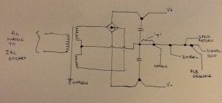
Here is how I do it.
1. charging currents to the filter caps flow through a separate ground connection.
2. a 'T' off the filter cap junction ensure no charging current contamination.
3. The ORDER OF THE GROUNDING IS CRITICAL
4. First the chassis ground (either direct or via a GND lifter), Zobel, then the speaker return, then decoupling, and finally signal.
5. The input signal GND and the decoupling GND are separated on the PCB by a 3-10 Ohm resistor.
6. The input connector is isolated from the chassis
7. The speaker GND connector is isolated from the chassis
8. Importantly, there is one, and only one connection to the chassis as shown
-110dB ref 1W out acheivable. And, its not a classic star ground arrangement, but if you look at it carefully, you can see it acheives what a star geound is supposed to acheive, but in a more structured way.
Like jneutron, I struggled to get hum free audio when I was young. My first breakthrough came when I culled the rectifier and filrter cap assembly from my blown up Marantz 240, and realized at the same time that the input signal connector ground has to be isolated from the chassis. My first completely hum/buzz free amp circa 1984.
My Ovation 250 amp uses the same approach shown in the picture and it is hum free - ear against the speaker cones and on a scope.
Note: the line shown between the primary and secondary below is the screen - it it not the transformer core.
Happy wiring!
🙂
Attachments
Last edited:
I note with more than casual interest, how you drew the capacitor connections..It's not often I see four lead capacitors drawn....it is becoming a lost practice.Here is how I do it.
RF and/or EMC experience, eh?
For others: a four lead capacitor is used to reduce the mutual inductance between the circuits before and after the cap...
j
What exactly is "decoupling"?Here is how I do it.
1. charging currents to the filter caps flow through a separate ground connection.
2. a 'T' off the filter cap junction ensure no charging current contamination.
3. The ORDER OF THE GROUNDING IS CRITICAL
4. First the chassis ground (either direct or via a GND lifter), Zobel, then the speaker return, then decoupling, and finally signal.
5. The input signal GND and the decoupling GND are separated on the PCB by a 3-10 Ohm resistor.
6. The input connector is isolated from the chassis
7. The speaker GND connector is isolated from the chassis
8. Importantly, there is one, and only one connection to the chassis as shown
-110dB ref 1W out acheivable. And, its not a classic star ground arrangement, but if you look at it carefully, you can see it acheives what a star geound is supposed to acheive, but in a more structured way.
Like jneutron, I struggled to get hum free audio when I was young. My first breakthrough came when I culled the rectifier and filrter cap assembly from my blown up Marantz 240, and realized at the same time that the input signal connector ground has to be isolated from the chassis. My first completely hum/buzz free amp circa 1984.
My Ovation 250 amp uses the same approach shown in the picture and it is hum free - ear against the speaker cones and on a scope.
Note: the line shown between the primary and secondary below is the screen - it it not the transformer core.
Happy wiring!
🙂
Jneutron, yes, and uV signal conditioning.
454Casull, this is the rail decoupling capacitors that sit on the amplifier PCB. The have their own return point if you swap the order, you end up injecting noise into the preceeding stages
Note that he order in which the decoupling capacitors are connected to the PCB ground is also important.
454Casull, this is the rail decoupling capacitors that sit on the amplifier PCB. The have their own return point if you swap the order, you end up injecting noise into the preceeding stages
Note that he order in which the decoupling capacitors are connected to the PCB ground is also important.
I still think the community could do with a sticky that provides a sound, and solid 'grounding principles strategy' for the layman. Keeping it simple and straight-forward, using illustrations to clearly communicate the 'typical' wiring scenario for a solid-state amp - specifically the grounding paths and when to use the star method, or other similar approaches.
I for one get so tired of reading opinion and hearing anecdotal evidence about critical topics that are rooted in math, physics and related science. It would seem to me that knowing the right and wrong ways to approach the principled science of grounding should be one such endeavor! Science and opinion are often confused on this forum. Newbie beware.
About 2 years ago I built my first chip amp for my son. I didn't even know about DIYAudio at the time. It was a crude construction, but I used the same principles I had used back in the 80's with other amps I messed around with. I even remember the typical grounding approach used on a couple of the Heathkit amps I built back in the day - where the focal point was the filter e-cap - using a t-bar arrangement. When I fired it up for the first time it worked and there was no audible hum.
Fast-forward 2 years....It took me several months to complete my latest build based on the LM4702. Mostly I was waiting on parts, but I was also trying to uncover the deep dark secrets about grounding on this forum. Truth is, the more I read, the more confused I became. Based on everything I read I thought I had a pretty good, well-thought out strategy. Not! I had hum. I went back and re-read Dave Davenport's excellent article on grounding. It revealed some new things and re-enforced some techniques I had used before. After making some minor changes that went against the star method, I was hum free. In all honesty, it's the quietest amp I've ever built.
Moral? Think science rather than opinion and what often sounds like anecdotal evidence. 😀
The sticky as you found out is already there......the community could do with a sticky ..................... and re-read Dave Davenport's excellent article on grounding. ............
I too find that as I understand more, that re-reading can further improve my understanding. That even applies when I thought I understood it the first time.
may be this will help...
http://en.wikipedia.org/wiki/Ground_loop_(electricity)
it says here about providing a constant ground by keeping the ground conductor zero resistance (rg) to isolate each circuit.
regards,
joel
http://en.wikipedia.org/wiki/Ground_loop_(electricity)
it says here about providing a constant ground by keeping the ground conductor zero resistance (rg) to isolate each circuit.
regards,
joel
link did not link.Did you mean: Ground loop (electricity)
Look for Ground loop
Wikipedia does not have an article with this exact name. Please search for Ground loop (electricity in Wikipedia to check for alternative titles or spellings.
Did you check your post after you posted it?
sorry, too many tabs....
it keeps me coming back to the same link.
well if your interested just type ground loop in google choose in wikipedia ground loop(electricity) I'm sure will clarify things in here.
try this:http://en.wikipedia.org/wiki/File:Ground_loop.svg
regards,
joel
it keeps me coming back to the same link.
well if your interested just type ground loop in google choose in wikipedia ground loop(electricity) I'm sure will clarify things in here.
try this:http://en.wikipedia.org/wiki/File:Ground_loop.svg
regards,
joel
Last edited:
You need to add a ) to the link in post 35. That will then take you to a Wikipedia article which is confused about ground loops, because as far as I can see it omits the main issue which is a magnetic hum field linking the loop.
The requirement for a zero resistance ground would be good, but can never be realised in practice so the real answer is to avoid current going to the wrong place.
The requirement for a zero resistance ground would be good, but can never be realised in practice so the real answer is to avoid current going to the wrong place.
- Status
- Not open for further replies.
- Home
- Amplifiers
- Solid State
- Quick guide on Grounding