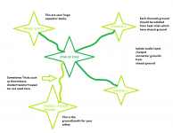
Between main star ground a chassis ground run 2 antiparalleled diodes and a 10R resistor for hum blocking.😉
Paulo,
the Disconnecting Network is optional.
Onaudio has shown this optional Network without specifying the detailed arrangement.
Onaudio,
I would prefer that your diagram also included the compulsory Permanent Chassis connection to PE.
the Disconnecting Network is optional.
Onaudio has shown this optional Network without specifying the detailed arrangement.
Onaudio,
I would prefer that your diagram also included the compulsory Permanent Chassis connection to PE.
Thank you Andrew. Do modify and post 🙂 . Appreciated.
I am hoping that this thread will remove some cob webs when it comes to grounding as well as addressing the real issues that go with it.
Its a free contribution thread.
I am hoping that this thread will remove some cob webs when it comes to grounding as well as addressing the real issues that go with it.
Its a free contribution thread.
I usually use the center point of the two main storage caps as the main start and branch everything off from there.
Tekko,
Please don't recommend your flawed method.
Your method leads directly to buzz on the audio signal due to current pulses in the transformer charging circuit.
Please don't recommend your flawed method.
Your method leads directly to buzz on the audio signal due to current pulses in the transformer charging circuit.
Where the two filter caps join, you should 'T' off and then star connect everthing. Do not make the junction of the caps your star ground.
When I was young I used to battle with this stuff, now I have it tapped and can build perfectly humless/buzzless audio.
When I was young I used to battle with this stuff, now I have it tapped and can build perfectly humless/buzzless audio.
Atleast any wires bearing current such as the speaker returns should in my opinion always go to the center point of the main storage caps and NOT to a secondary star.
My lafet amp does have a secondary star on the drive board where the signal grounds go along with some filter caps, and then a single wire from there to the center point of the main caps, there is no hum what so ever, u have to give it a signal to tell if its on or not.
My lafet amp does have a secondary star on the drive board where the signal grounds go along with some filter caps, and then a single wire from there to the center point of the main caps, there is no hum what so ever, u have to give it a signal to tell if its on or not.
This is the grounding scheme of the lafet amp: http://i.imgur.com/JDmSQ.png
That is what seem most logical to me.
That is what seem most logical to me.
Tekko,
your thinking and implementation is flawed.
You show an implementation in the PICs Thread and this seems to confirm.
your thinking and implementation is flawed.
You show an implementation in the PICs Thread and this seems to confirm.
So having signal and speaker ground sharing the same ground lead is the right way then ?
As in having smaller storage caps on each channel which center point is each channels speaker ground with a 10 ohm resistor between it and signal ground and then three leads per channel to the main psu, is this what your trying to say ?
If yes, then that for sure hum loudly as signal and speaker ground shares the same wires.
The speaker ground must have the same reference as the input signal, otherwise you are treating the difference between these two points as part of the signal. The arrangement shown in the link from post 11 ensures that ripple current feeding the second set of caps gets injected into the speakers. I assume this is not what you want.
http://i.imgur.com/fA390.png <-- but this just seems plain wrong, but it sounds on AndrewT like that is the right way.
But to me is just seems plain wrong.
But to me is just seems plain wrong.
Andrew never asked you to insert 10 ohm resistors in random places. Neither did I. Why not try thinking, instead of poking fun at people trying to help you?
im not changing something that works fine for me, my ground scheme stays and i'll continue to recommend it to beginners that come to me for help no matter what ppl say.
And people like me and Andrew will continue to recommend that people avoid your flawed scheme and instead do some thinking about where the currents go.
I can't see your remote server diagram, so I cannot comment on it.
I am talking about the pic you posted and the way you described in post10.
I am talking about the pic you posted and the way you described in post10.
Tekko, could you please try a quick sim experiment? With the circuit grounded as you show, could you place a few ohms in the lead going from PCB ground to the PS ground? Now could you do the same thing, but moving the speaker grounds to the PCB ground point?
I would do this, but I'm SPICE-challenged.😀
I would do this, but I'm SPICE-challenged.😀
- Status
- Not open for further replies.
- Home
- Amplifiers
- Solid State
- Quick guide on Grounding