The Aleph design creates a lot of internal heat. I know, I've got an Aleph 4. They tend to cook the capacitors. I've had to change all the big C's twice in 12 years, they are not cheap to replace.
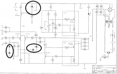
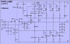
Capacitor in parallel to D5 (Z5 on original schematic) better NP or electrolytic?
Also, ina thread from Pass, he suggested to also put a capacitor in parallel to the other zener (Z1,Z2 and Z3,Z4) value between 1 and 4,7uF
point me to exact schematic you're speaking about
ZM,
in case a capacitor is put in parallel to Z5, Z1-Z2 and Z3-Z4 must it be electrolytic or non polarized?
thank you
in case a capacitor is put in parallel to Z5, Z1-Z2 and Z3-Z4 must it be electrolytic or non polarized?
thank you
Z5 - OK , put 10uF elko
Z1-Z4 - whatever you put there , you'll make silencer instead of amplifier

(in short - don't do that!)
Z1-Z4 - whatever you put there , you'll make silencer instead of amplifier
(in short - don't do that!)
Thanks ZM!
also, concerning the power supply, would it be good to put a MKP capacitor (0.22-0.33uF) on the primary winding ot the tranny and two MKP (0.47-0.68uF) on each secondary winding?
I would not build a power supply with CRC or CLC filter
thank you again
also, concerning the power supply, would it be good to put a MKP capacitor (0.22-0.33uF) on the primary winding ot the tranny and two MKP (0.47-0.68uF) on each secondary winding?
I would not build a power supply with CRC or CLC filter
thank you again
don't do that with xformer
find and read Quasimodo and Cheapomodo threads here
if you are not sure in what you're doing , better don't do anything
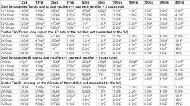
this table is good , but as semi-patch , not proper one , made after adequate test:
find and read Quasimodo and Cheapomodo threads here
if you are not sure in what you're doing , better don't do anything
this table is good , but as semi-patch , not proper one , made after adequate test:
Attachments
ok ZM!
maybe better to buy the soft start board together with the speaker protection one from the diyaudio store.
maybe better to buy the soft start board together with the speaker protection one from the diyaudio store.
Hello ZM,
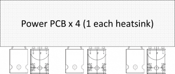
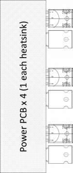
PCB development is in progress, I finally decided for the traditional 2 layers!
question about the output devices (IRFP240):
- the original design has 3 paralleled devices while the modified M10 has 4 in parallel. is there any advantage to have 4 instead of 3?
- power transformer output voltage question, would it be possible to have 2x26Vac as secondary?
- 26x1.41=36.7 - 1.4 =35.3Vdc
the original A5 asks for ±34Vdc voltage rails. don't think an addition volt and a half would be a pain.
thank you
Attachments
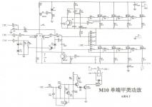
more output pairs , if you don't change anything - more heat and more grunt on 4R speakers
don't forget to alter current sense resistor group , according to number of mosfets .... in fact - that's already done on that schm you posted
for 34Vdc rails , compute AC as DC/1.25
so around 28Vac
1.41 is for lightly or non- loaded rectification/filter
don't forget to alter current sense resistor group , according to number of mosfets .... in fact - that's already done on that schm you posted
for 34Vdc rails , compute AC as DC/1.25
so around 28Vac
1.41 is for lightly or non- loaded rectification/filter
Hello Diegod,
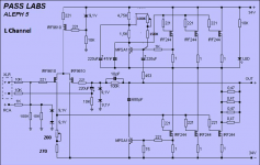
I just noticed your questions about Aleph 5 and thought I'd add my two cents because I built a set of amps similar to what you're investigating.
I built a pair of Aleph 5 mono's with 4 outputs instead of the normal sets of 3. I've biased them up a bit and have them at 600mA per device on 33VDC rails. I'm using an Antek 500VA - 25V X 2 transformer in each mono amp. My incoming AC voltage is a bit high here at 125VAC so I get a little bump on the rails of my amps. If it was more normal at 115 -120VAC then my DC rails would be < 32VDC.
I recently went through the amps and installed SJ313's for the diff pairs and cleaned a few other problems up. I posted some info about the amps with some measurements here.
- Status
- Not open for further replies.
- Home
- Amplifiers
- Pass Labs
- Questions about the Aleph 5