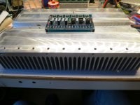
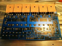
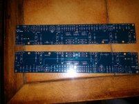
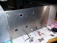
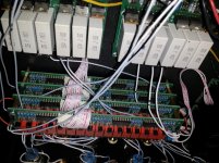
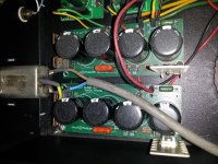
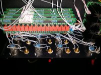
As requested pictures !
(i'll post schematic with measuments asap)
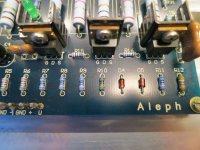
Other strange thing : resistance Source (Q6/Q8) to chassis = 7MegOhm
The good channel gives 9MegOhm.
(i'll post schematic with measuments asap)
Other strange thing : resistance Source (Q6/Q8) to chassis = 7MegOhm
The good channel gives 9MegOhm.
Attachments

Last edited:
!! Breakthrough !!
I guess problem found !
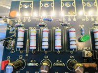
Last attempt before removing Q6 to Q8 i decided to place a pot at position R11.
Now at 390 ohms, but 15mV offset.
I'll leave it in for a while to heat up. but things are looking good so far !!!
(cold air over Q1,Q2,Q3 drops offset to 3mV)
(i should have listened to this advice much earlier...
I guess problem found !
Last attempt before removing Q6 to Q8 i decided to place a pot at position R11.
Now at 390 ohms, but 15mV offset.
I'll leave it in for a while to heat up. but things are looking good so far !!!
(cold air over Q1,Q2,Q3 drops offset to 3mV)
(i should have listened to this advice much earlier...
I guess, case closed.
Waited a while and measured offset again. Changed R11 to 402(390+12) ohms and all is good now.
Just in time before Xmas
Now time to enjoy good food, a nice drink and some nice tunes.
Regards,
Nick

Waited a while and measured offset again. Changed R11 to 402(390+12) ohms and all is good now.
Just in time before Xmas
Now time to enjoy good food, a nice drink and some nice tunes.
Regards,
Nick
Happy New Year everyone
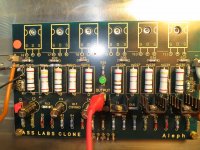
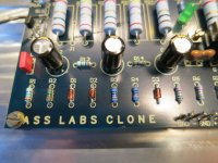
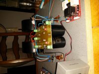
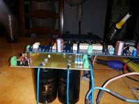
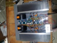
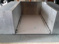
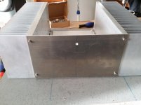
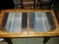
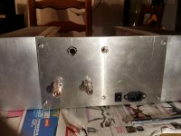
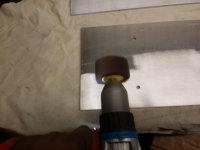
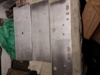
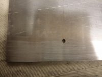
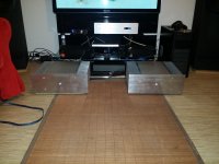
As promised here are the pictures of the construction of 5 aleph.
the result is how to say: Breathtaking with aleph P 1.7
Thank you for your help and your advice you are super awesome
As promised here are the pictures of the construction of 5 aleph.
the result is how to say: Breathtaking with aleph P 1.7
Thank you for your help and your advice you are super awesome

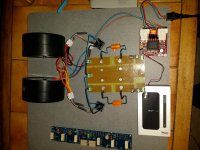
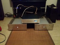
second elements
The box part 1
The box part 1
Attachments
-
 20151115_145539.jpg486.6 KB · Views: 121
 -
 20151115_145622.jpg979.6 KB · Views: 82
 -
 20151118_220639.jpg493.2 KB · Views: 71
 -
 20151119_182701.jpg699.2 KB · Views: 72
 -
 20151120_214053.jpg811.5 KB · Views: 78
 -
 20151120_223238_Richtone(HDR).jpg762.6 KB · Views: 71
 -
 20151120_225537_Richtone(HDR).jpg997.4 KB · Views: 79
 -
 20151120_225623_Richtone(HDR).jpg528.1 KB · Views: 90
 -
 20151124_192401.jpg500 KB · Views: 74
 -
 20151124_194315.jpg565.1 KB · Views: 65
![20160101_125050[1].jpg](/community/data/attachments/470/470534-715b37c3d8626cb14dbfd53b29b84765.jpg?hash=cVs3w9hibL)
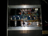
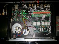

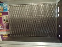
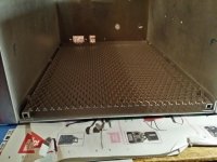
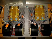
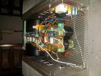
the box
I used the metal mesh to secure all components and have no attachment to the bottom of the box
Nice! Big mono blocks. Why did you put the wire mesh in the box?
I used the metal mesh to secure all components and have no attachment to the bottom of the box
Hi!
I am building an Aleph 5 clone and I would like to know if it is at all possible to change the outputs from hexfets to lateral FETS? And if possible, what has to be changed? I was thinking about something like this: FQA19N20C or FQA70N15.
I have no experience from experimenting with power FETS and I would be grateful for any help.
If substitution is not possible or advisable, I do have the IRFP240 and the IRFP260 in my drawer; which one is the best choice?
Thanks a lot, I really look forward to powering up the boards!
Yes you can do it. I am converting a Zen 4 to Lateral mosfet. I am unaware that Fairchild make lateral mosfets though.
If you have a circuit diagram that would help.
Most likely you will need to add a trimpot on the drain of Input mosfet for setting dc offset.
You will also need to change gate resistance values.
If you have a circuit diagram that would help.
Most likely you will need to add a trimpot on the drain of Input mosfet for setting dc offset.
You will also need to change gate resistance values.
Last edited:
Lateral FETS with Aleph 5
Thanks 2 picoDumbs! (May I call you "pico"? My clone is an M10 from China, and the main difference from the original, that I find, is 4 pairs of output FETS instead of 3.
And the addition of the speaker protection is quite nice!
Thanks 2 picoDumbs! (May I call you "pico"? My clone is an M10 from China, and the main difference from the original, that I find, is 4 pairs of output FETS instead of 3.
And the addition of the speaker protection is quite nice!
Attachments
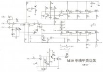
Maybe I am wrong in assuming these FETS are lateral FETS? The datasheet says "QFET", and they are designed for switching purposes as well as audio amplifiers.
You will most likely need to change the value of R13 to set dc offset to Zero, depending on what mosfets you decide to use.
If you can fit a trimpot in there, it will add flexibilty in setting the dc offset.
Edit: I am reconsidering that thought, I'm starting to think the combination of Q4 and Q5 will ensure a zero dc offset, but possibly changing R13 to a higher value maybe necessary for some devices to ensure the device is on, certainly not necessary for true Lateral Mosfets. I'll Let Zen Mod confirm as he is far more experienced with original Aleph series.
If you already have IRFP240, there is absolutely nothing wrong with those devices though.
If you have 2sj313 that would be a worthwhile upgrade over irf9610.
Last edited:
I wouldn't bother chasing different outputs - just use IRFP240
they're peanut priced , so either buy them matched or buy enough to match your own (at 500mA)
agree about 313
also - it's wise to put 470R trimpot instead of R13 (set offset) , and series combo fo 150K fixed resistor+100K trimpot , in place of R17 (set Iq)
all that ref. to schm posted in #56
they're peanut priced , so either buy them matched or buy enough to match your own (at 500mA)
agree about 313
also - it's wise to put 470R trimpot instead of R13 (set offset) , and series combo fo 150K fixed resistor+100K trimpot , in place of R17 (set Iq)
all that ref. to schm posted in #56
Just one other comment.
I think there is a mistake with that circuit. Most Aleph circuits I have seen have C3 connected between R19 and Q5 as well as connected to R17. Your circuit doesn't show that.
I think there is a mistake with that circuit. Most Aleph circuits I have seen have C3 connected between R19 and Q5 as well as connected to R17. Your circuit doesn't show that.
- Status
- Not open for further replies.
- Home
- Amplifiers
- Pass Labs
- Questions about the Aleph 5