I just picked up an incredibly simple push/pull amp with just 1 12AX7 and two 6V6. That's possible because they used an interstage transformer for the phase inverter, instead of another tube. For guitar, of course; its obviously completely unsuitable for bass. Schematic:
Attachments
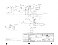
This is the later 6V6 version, not the earlier 6BQ5.
See that 15K resistor across the primary of the interstage transformer? Is that supposed to damp the transformer inductance from ringing or something? Or is it to get a more suitable load when using whatever transformer they had handy? Does the 026847 transformer number mean anything to anybody?
Oh, I guess that 15K is to deliver the B supply to the plate DOH! And the interstage transformer primary is across that plate resistor rather than to ground. I can't say I've seen that before...but there's a lot of things I haven't seen yet.
Last edited:
If you plug into only jack #1, it's going thru two 68K resistors in parallel, or 34K.
If you plug into only jack #2, it's going thru only one 68K resistor.
If you plug into both, each goes thru a different 68K resistor.
So jack #1 should have a bit more gain for maybe a bit more grit jack?
I assume the miniscule difference in how each loads the guitar pickups is inconsequential?
Why the input coupling cap? And why such a small value, I'd expect more like an .047?
What about that 470K grid-stopper? Can I get more sparking highs with a 1M or even 2m?
I suspect some of these things in the original design were a nod to the "bass" amp claim...which is a pointless objective these days when there are better bass options.
The 026847 is a Fender part number.
Yes, I was just curious whether it was familiar to anyone, basic specs, used elsewhere, manufacturer codes, etc.?
I really like that it has fewer tubes to introduce noise. Transformer shouldn't limit bandwidth much as the turns ratio should be pretty conservative.
I hope the iron they used is adequate for the job; I'm hoping that though this was their cheaper line that they used better transformers as they were claiming it made bass.
I hope the iron they used is adequate for the job; I'm hoping that though this was their cheaper line that they used better transformers as they were claiming it made bass.
I'd be inclined to change on of the 68K resistors to a lower value, so that I have a lower-gain input and a higher-gain input.
Other people have changed the tone control to the "Harvard" model tone control. I'm inclined to try that and fiddle with the capacitor values. There's no gain or power to waste in this thing!
I'm inclined to install a speaker jack, so I can use variable crossover-type tone controls and an Aiken reactive load, kind of an "ultimate" master volume as late in the signal chain as possible.
I wish I had more experience with 'sag' and it recovery, and I wish I really knew whether larger filter caps would hurt that? Could be an interesting application for a VVR?
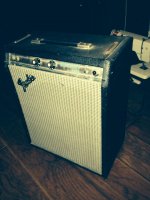
I'll know more when it actually arrives, this was an impulse purchase because the price was right; I was the only bidder on eBay. Comparable little Fender amps are in more demand and bringing 5 or 6 times the price I paid.
It could be interesting to keep it looking stock but changing the volume pot to a push/pull to pull for bright cap across the volume pot.
It could be interesting to also use a push/pull pot for the tone control, and have it select one small value cap across the cathode resistor or add a second one in parallel, like the "deep" switch in my favorite schematic for the "Angela" amp.
That .01 interstage coupling cap could be a .047 from what I've seen elsewhere.
It's got a more recent small-voicecoil Jensen Fender alnico speaker, which would probably reproduce the lows if the amps passed them, without getting flabby and flatulent.
I don't see any feedback loop of any kind.
A small choke instead of that 10K dropping resistor might make the front end quieter. It might be worth changing all the plate resistors to some quiet metal-film type. It might be worth referencing the filament circuit to a 1/10 voltage divider across the B supply to reduce hum.
This is all speculation as I don't even have it yet! But...all comments, any real experience with these, or any cool ideas are very welcome.
It's the later model, so it should already have a 3-prong plug etc.
This is all speculation as I don't even have it yet! But...all comments, any real experience with these, or any cool ideas are very welcome.
It's the later model, so it should already have a 3-prong plug etc.
They're claiming 12 watts at 2khz, but supposedly this 6V6GTA model puts out more than the previous 6BQ5 but it says the same thing on both schematics.
Wow, eleven posts in an hour and five minutes. Try gathering your thoughts so it is easier to read.
In no particular order:
You already HAVE low and high gain input jacks, that is what the two resistors do. In the high gain jack. If you plug into J1, the two resistors are in parallel for 34k, and the signal flows through it. Plug into J2, and it all changes. From J2, the signal flows through the other resistor, but the remaining one is now grounded through J1. The tube gets the signal from the junction of the two. In other words, there are now two 68k in series from the input to ground and the tube gets the signal from the middle. This is a basic 2/1 voltage divider, so using J2 cuts the signal input exactly in half, which is a 6db reduction. Thus high and low gain. Fender has used this arrangement for decades on end. And a great deal of the rest of the amp world do as well. yes, if you plug something into both, then each has a 68k in series and the resistors do their best to mix it. But really, who plugs two instruments into one channel?
An old trick is to plug the guitar into one jack, and then a simple shorting stomp switch into the other jack. Now stepping on the switch switches from high gain to low.
Most of the current to the driver plate comes through the primary of that transformer.
The input cap blocks any DC riding on the input, but mainly serves to limit the low end response, which would suck power and probably overdrive the speaker.
For transformer manufacture codes, you tell us, look on the part.
Remember, the amps are about circuits, not parts. You saw .047 elsewhere, but it was also in a different circuit. Just changing the one part because some othe circuit used it in similar position, is not a good reason. I am not saying it is a bad idea ultimately, but do it for the right reasons.
The 10k resistor in the B+ is there to drop the B+ by 40v for the preamp, as well as be part of the decoupling. replacing it with a choke would raise that B+ to closer to the screen voltage. If the first two B+ filter caps are good, I doubt a choke will make it any quieter.
If you have not yet taken possession of the amp, perhaps a good listen first before trying to modify the thing for hum/noise we do not yet know exists. This is not a high gain amp.
As to making a B+ voltage divider for the heaters, several thoughts. First, we are assuming you have some hum from that source, you may well not. But mainly, if you look at the schematic,you will see one side of the heater string is grounded. To elevate the heaters, you need to rewire so neither side is grounded. And rather than create a B+ divider, I'd simply connect the string to the power tube cathodes. That is a free +16v already sitting there, and that is plenty for the job.
In no particular order:
You already HAVE low and high gain input jacks, that is what the two resistors do. In the high gain jack. If you plug into J1, the two resistors are in parallel for 34k, and the signal flows through it. Plug into J2, and it all changes. From J2, the signal flows through the other resistor, but the remaining one is now grounded through J1. The tube gets the signal from the junction of the two. In other words, there are now two 68k in series from the input to ground and the tube gets the signal from the middle. This is a basic 2/1 voltage divider, so using J2 cuts the signal input exactly in half, which is a 6db reduction. Thus high and low gain. Fender has used this arrangement for decades on end. And a great deal of the rest of the amp world do as well. yes, if you plug something into both, then each has a 68k in series and the resistors do their best to mix it. But really, who plugs two instruments into one channel?
An old trick is to plug the guitar into one jack, and then a simple shorting stomp switch into the other jack. Now stepping on the switch switches from high gain to low.
Most of the current to the driver plate comes through the primary of that transformer.
The input cap blocks any DC riding on the input, but mainly serves to limit the low end response, which would suck power and probably overdrive the speaker.
For transformer manufacture codes, you tell us, look on the part.
That .01 interstage coupling cap could be a .047 from what I've seen elsewhere.
Remember, the amps are about circuits, not parts. You saw .047 elsewhere, but it was also in a different circuit. Just changing the one part because some othe circuit used it in similar position, is not a good reason. I am not saying it is a bad idea ultimately, but do it for the right reasons.
The 10k resistor in the B+ is there to drop the B+ by 40v for the preamp, as well as be part of the decoupling. replacing it with a choke would raise that B+ to closer to the screen voltage. If the first two B+ filter caps are good, I doubt a choke will make it any quieter.
If you have not yet taken possession of the amp, perhaps a good listen first before trying to modify the thing for hum/noise we do not yet know exists. This is not a high gain amp.
As to making a B+ voltage divider for the heaters, several thoughts. First, we are assuming you have some hum from that source, you may well not. But mainly, if you look at the schematic,you will see one side of the heater string is grounded. To elevate the heaters, you need to rewire so neither side is grounded. And rather than create a B+ divider, I'd simply connect the string to the power tube cathodes. That is a free +16v already sitting there, and that is plenty for the job.
Yes, I was just curious whether it was familiar to anyone, basic specs, used elsewhere, manufacturer codes, etc.?
I did find a gut shot of this amp on the web and it had the 606 EIA code which is Schumacher. usually, I haven't found any other info when trying to cross-reference these numbers. Also not sure but have heard these interstage trannies kind of degrade the sound, but not too sure. Obviously, these are not very common.
Also that 470k resistor isn't a grid stopper, it is a grid leak and if you want more gain at the input, change it to 1Meg. This is as high as you should go. It shouldn't affect the freq. response too much, just more gain because less signal is shunted to ground.
With 290v on the plates, I suppose this is why the 6V6 version has the same output as the 6BQ5 version. Pretty conservative voltage. Since these are usually reasonably priced, I have often considered this amp for guitar with some mods. Keep us updated.
Last edited:
ENZO thanks for your indulgence reading my over-enthusiastic dump and taking your time to reply, you've always been a guiding light.
Thanks so much for pointing out my misread of the input jack schematic, now that new paradigm is forever etched in my brain for future recognition! One of my early Alembic preamps had something sort of similar except jack #1 was straight in without any series resistor, like some Mesa amps, but still did a 50/50 mix if you used both for a stereo guitar like an ES-345; I don't know whether they used more contacts on the jack...my later Alembic didn't have that 'feature'. There's no way I would want a long high-gain shielded cable to a stomp box to switch, but it would be interesting to mount a teensie toggle in a big shielded jack body, to have a hi/lo switch for instant comparison.
Obviously I need to actually get and play and listen before I start dreaming up mods!
Yes, "Most of the current to the driver plate comes through the primary of that transformer" like it does on an normal output transformer primary. So why is there a resistor too? Compensating for a poor choice of transformer? Or perhaps just burning off some extra power to avoid saturating the transformer or burning the primary? Or some kind of protection for the transformer, or tuning resonance??? Or is that just touch-up circuit-tweaking?
Yes, I figure there were few powered pickups in those days and they should have their own DC-blocking. So why the input coupling cap? Building on what you said: they sell this as a bass amp yet there's no way it could handle much real low bass, better to limit bandwidth and have an amp that's reliable and won't get into blocking or speaker blat. It's not a bass amp, it's an amp that will tolerate and survive a bass. I'm still hoping they used good enough transformers to still get good bass at 6-sting guitar ferquencies if I relax those bandwidth limitiations some...keeping in mind of course that this is not an hi-fi amp and limiting bandwidth is part of good instrument amp engineering.
The other circuits where I see a much larger interstage coupling cap were again between two 12AX7 stages, and the difference here is the tone control and the impedance it presents compared to the normal stack. Which from what I hear doesn't really work but indeed I get what you're saying. So...I probably really need a new tone control and coupling cap to work together, or a lot of experimenting.
I understand what you're saying about the choke, but that's true of just about every guitar amp that does or doesn't use a choke. This one would not need to handle much current, as it only powers one constant-current class-a tube, and it's not likely to saturate or change inductance value much. But this is not like my single-ended experiments, this one will have issues of sag compression and release to remain cognizant of, or I could ruin the 'touch response' that some people love...do I want that output sag compression to also cause more input compression due to power supply drop? Guitar mojo sure complicates the purity of engineering LOL. I would also tweak with a resistor to get the desired drop. Just a thought, with the exact same issues as with any other push/pull amp.
Yes, I saw that one side of the heater was grounded. But I'm concerned about what you are suggesting...I'd expect the raised cathode to vary more with the signal than the B supply being somewhat stiff and varying only with long-term demands following the volume envelope with some delay rather than carrying signal. It's pretty common to make the 1/10th divider and it doesn't waste much current as it's easy to lift the heaters. I've had good results, why mess with success?
Indeed, I'm getting way ahead of myself! Noise is always my fear about vintage equipment, the one thing I don't like about vintage tube equipment; we were much more tolerant in those days. My old pre-CBs strat and my Melody Maker single-coils hummed like a refrigerator anyway. So did my stereo (mono?). That was before they started making the middle pickup on a strat with reverse magnet and winding to buck or any 5-position switch much less double-stacks, Lace sensors, noiseless, N3, etc. Modern tube amps hold themselves to the low-noise standards of quality transistor equipment. Whether for low-level practice or recording or to be re-amped or mic'd...lowering the noise is often a great alternative to increasing the output. When the noise is inaudible to my ear, I want it lower for when I mic it or record it. Now if I just applied that lesson to my own writing style in my posts....less noise requires less volume LOL.
Last edited:
boobtube, the internet is incredible. You've seen the guts before I have LOL.
Teach me: if that's a grid leak, what's a grid stopper?
I'd heard that the resistor in that position, whatever it's called, is very sensitive to noise in that input first stage especially, and some aspects of the resistor noise (specifically the thermal noise) is related to its value, with bigger values being noisier.
Just by chance I have a few Hammond 270CAX with a little bit more voltage...but too soon to consider. But immediately upon seeing the schematic my mind went immediately to question whether transformer upgrades all around would help. When they made these I suspect that distortion was a less desirable trait, and if the preamp limited first they wouldn't worry about whether the transformer would handle that beautiful tube distortion accurately LOL.
But I haven't even put a scope on the various stages myself yet!
Last edited:
This thing might really sing with an Aiken reactive load and a FET stomp box to front-end it. Not all the time of course...
The grid stopper is the resistor in series with the input and the grid of the first tube, the 68k. It is there to "stop" RF interference. If this resistor causes noise, this noise is amplified the most since it is in the first stage, so it will be loudest. Most amps have done away with that cap also in series. It's purpose has already been addressed but mainly to block any DC on the input and to tailor low end response.
The 470k resistor is the grid leak resistor. It provides a reference to ground for the grid, otherwise it can float at an unknown voltage causing the tube to be unstable. If this value is higher, less signal will be shunted to ground, thus giving the grid a stronger signal.
The 470k resistor is the grid leak resistor. It provides a reference to ground for the grid, otherwise it can float at an unknown voltage causing the tube to be unstable. If this value is higher, less signal will be shunted to ground, thus giving the grid a stronger signal.
Last edited:
I forgot to address the value of the grid stopper resistor WRT noise. You are correct about a higher value generally creating more noise. A lot of amps have carried over the 68k value from old Fender designs. This value really isn't necessary. A lower value such as 22k or so will do. Of course when the hot input parallels two 68k then you end up with 34k. I have found an overall value(single or paralleled) of around 22k will suffice. A lot of builders will put metal film or other low noise resistors here.
Also, with these older designs, they were trying to eliminate distortion, but with this amp, I don't see how this can happen. Thus, makes a good guitar amp or the basis for one. Lower voltages tend to have a more distorted signal, less headroom and clean signal available.
Here is a really good primer on the preamp and a really good book to order. Scroll down to page 21 for B+ plate voltage and load resistors on distortion:
http://www.valvewizard.co.uk/Common_Gain_Stage.pdf
I had an intriguing idea.
Studying that resistor across the primary of that interstage PI / driver transformer, it's obvious to me that the difficulty that transformer will face is the same as with a single-ended output transformer. The primary has all that darned DC on it! Really tough for the winding and the core. The obvious answer is parafeed IMHO. The AC signal is relatively low power and I'm guessing about a .47uf cap would pass the limited bandwidth required for guitar. The exact formula for that coupling cap would be:
C = 159155/(rp + Rload)/Frequency
I have no idea whether the existing interstage has any air gap in the core like an output transformer, but regardless this should be an improvement. And we can probably lose that resistor across the primary.
A high-quality air-gapped inductor is called for in the common parafeed configuration to deliver the B+ supply to the anode plate. But a resistor might suffice, heck it works for normal preamp stages. Then technically it's not really called parafeed, it's "RC coupled" and subject to a lot of resonances I wouldn't want to calculate. So it's ripe for experimentation at the price of 1 cap and 1 resistor.
Last edited:
- Status
- Not open for further replies.
- Home
- Live Sound
- Instruments and Amps
- questions about Fender Musicmaster Bass amp schematic