What you'd really want in a toroidal output transformer maker is someone that uses advanced techniques like progressive winding to reduce capacitance. The leakage inductance seems taken care of by the nature of the toroidal design, it's the winding capacitance that appears to present most of the problem. This was pretty much driven home to me in my attempt to use some bog-standard toroidal transformers for a parafeed design.
One thing I noticed using standard toroidal power transformers in parafeed is that the high capacitance causes roll-off soon after 20kHz,with no marked tendency for the gain to poke back up through 0dB after crossover. The higher intrawinding capacitance may be a contributing factor in this. Unfortunately, with a closed loop design, I was only getting about 30 degrees of phase margin.
As I have mentioned before, I may try tinkering around with output Zobel networks and some mild compensation to see if I can improve the phase margin for closed loop operation. Getting the parafeed design to work closed loop with cheap power toroids would be a nice coup.
As I have mentioned before, I may try tinkering around with output Zobel networks and some mild compensation to see if I can improve the phase margin for closed loop operation. Getting the parafeed design to work closed loop with cheap power toroids would be a nice coup.
tI've had luck with the high frequency roll off by biasing the output tube to idle at a higher current. I don't remember my exact results off hand, but 30mA seemed to be adequate for the 10VA models up to 30 or 40 kHz. But again, for headamps, I am not swinging large voltage
Last edited:
If anything, the tubes in my parafeed setup were running pretty hot, so I'll actually be taking measures to tone them down some. I'll see if it has any effect on the gain=phase when I have a chance to hook the amp up to the gain-phase analyzer again. The triode #2 section of the 6/13DR7 I'm using is pretty respectable, with a 925 ohm plate resistance and a sweet set of curves.
It's a bit surprising that you're having problems with a valve with lower than 1k plate resistance; are you suggesting that the capacitance of the toroids you are using is more than a couple of nanofarads?
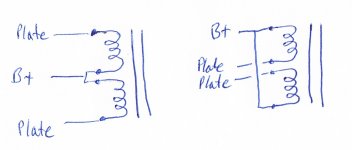
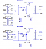
There are two ways to connect the 115V primaries. With some transformers others have reported that one connection will have much better high frequency response than the other - you have to try both to see which is better. The couple I've tried it made no difference (might depend on the winding method used), but worth a try. The attached sketch assumes a push-pull amp.
Attachments
piano3 -
It's not as horrible as all that. -6dB gain, -45dB phase is at around 50 kHz, and 0dB crossover is at 95 kHz. I guess it would be interesting to drag one of the toroids in to work and run its numbers using our HP4194A impedance analyzer. It can give guesstimate on primary shunt capacitance if you come up with the right equivalent circuit.
One advantage of using a somewhat higher VA rating might be to get the number of primary turns down, and perhaps the primary shunt capacitance as well. Having said that the lower number of turns may be balanced out by the longer mean length per turn, leaving the capacitance about the same. It wouldn't hurt to measure a couple of samples to see if there is any advantage.
The 50 VA ones which I normally use drop from typically 140H at 6V, 50Hz excitation to about 85H at 1V. As far as I remember, the 100VA ones dropped to maybe 45H, but this would be no problem for the kind of trioded sweeps or regulator triodes that several members here have used.
That's probably not all that unusual, as the permeability of silicon steel tends to drop off at low excitation levels. High nickel alloys tend to keep their permeability at low level, which is why it's common practice to slip some nickel lams into a parafeed transformer stack.
Last edited:
Ok... I finally got my new scope today, and after an hour or two of getting used to a newfangled digital device, I was able to take a few measurements. The voltage amplifier was a 4p1l to 4p1l stereo headphone amp rewired to cascade. The first transformer tested was a 115+115:12+12 10 VA Antek with the primarys in series and the secondaries in series. Secondary was loaded with a 50 ohm resistor giving a reflected load of 4.59K. Close enough. Measurements were taken from the secondary. Saturation was predicted at 20Hz with (230vrms(sqrt2))2×(20Hz/50Hz) resulting in 260.21vpp across the primary. Divided by the turns ratio (9.58) results in 27.16 vpp across the secondary. The voltage amplifier was fed an increasing signal until visible saturation took place, which ended up being 26.8 vpp. Transformed, that is 256.74 volts peak to peak.
Using the same amplifier, I wired up a rat's nest involving two 115+115:5+5 10VA Anteks with all primaries in series and all secondaries in series. The secondary was loaded with an 8 ohm resistor. Given the limitations of the amplifier used, I could not get saturation at 20Hz, even with very severe clipping. I plan to try with a choke loaded 6p36s in the near future. With both transformers in series, I measured -3db rolloff at 27kHz. The output tube was biased at 50mA.
I will continue experimenting
Last edited:
Antek Toroidal Power Transformer as an O/P Transformer
Having just been browsing the antek site, Are you aware that they now offer a small range of Toroidal Output transformers for valve amp use about 6 of them in varying impedance & power output ratings.
Having just been browsing the antek site, Are you aware that they now offer a small range of Toroidal Output transformers for valve amp use about 6 of them in varying impedance & power output ratings.

Interleaving the winding gives you "full fidelity" (30Hz - 50kHz+)
If anyone has a better term than "interleaving" I'm all ears BTW.
I get 110~ watts from PPP 6P45S in triode connection with this set up using a pair of VPT18-13800...
It is a great idea but with series primaries AND series secondaries how would you guarantee even voltage distribution (loading) between transformers?
Would'nt parallel secondaries work better?
Attachments
You don't, but there's no need apparently. The two act as one.
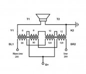
Also, I'm not sure who annotated that graphic, but those numbers (8, 12, 80, 120) mean nothing to me as both coils are identical transformers and so if they represent voltages, each primary is 115, each secondary is 9 when using VPT18 series xfmrs.
If you parallel the secondaries, you change the impedance ratio. Instead of 1k3:8 you'd get 5k2:8R or 21k:8R - both unsuitable for triode strapped sweep tubes
Last edited:
OK, then next experiment will be to try a substation transformer.
For what? Powering a transmitter? 🙄
No, because it has still larger core size.
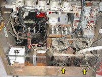
Not quite substation size, but small 2-3KVA pole transformers currently in service as plate voltage transformers in an old home built transmitter here.
The high voltage side (4800 CT) is the primary, which is the opposite of the usual plate transformer which is powered by 120/240V.
1. the transformers are installed in the transmitter. Not likely to be replaced unless more appropriate plate transformers can be had. This has not stopped me from thinking about this thread and a large VT subwoofer amp (I already have 150-175W full-range tube amps).
However, it would be an huge impractical experiment to find out if it would work and how well. If it was perfect (LOL) there could be, based on total size of the pair of transformers =6KVA@60hz, 1500W@30Hz, 750W@21Hz according to Vanderveen's paper, but that one statement does not tell the entire story.
Anyway I'm not going to try this because I doubt the 'nuances' of tubes will be appreciated in what comes out of a subwoofer, and there is a stack of solid state Ling TP850 amps here for subwoofer powering.
It's just a thought experiment brought on by an excess of high power components.
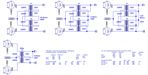
2. 3-500Z OPT Hookup using pole transformers. choice of 5 or 1.25 Ohms. 3-500Zs can make up to 1400 Watts.
3. Driving high mu triodes, especially those with large peak grid currents like 3-500Z. This has been done very successfully in that transmitter. When I switched from 304T tubes to more common 3-500Zs, I found those grids have about 1/4 the driving impedance of 304Ts and the original driver transf. was a 40W unit for 833s and 450TH types, it could not efficiently drive 3-500Zs. So here are proven Edcor solutions for that. And also the smaller units work well with 811As. Power rating is overkill but the performance as drivers is perfect.
Attachments
Hi Nectarpuke,I have used the 10 VA Anteks for a few single ended parafeed headamps with success. The highest voltage swing through the primary was 20 volts, so saturation is a nonissue. I avoid feedback all together, so I can't comment on the stability. I have also used 10VA Anteks for a 6N6P parafeed push pull output, but I don't recall ever taking measurements. I do remember it having very clean and deep bass, and was easily the most detailed push pull circuit I have heard to date... but I have only built a few.
I have been looking for amplifier circuits for the 6N6P dual triodes. I was hoping you would post your push pull parafeed schematic please and thankyou. cheers B12.
Sorry, but I don't have a schematic for that build as it was made a number of years ago. I believe I used the recommended operating point from the data sheet with a NiCad battery on the cathode. The plates were loaded with CCS's and adjusted to keep the current balanced between the differential triodes. I used a 230v to 5v Antek transformer with the coupling capacitor placed in series with the primary windings at what could be considered the center tap. The phase inverter / driver stage was a 6sn7 with an LM317 in CCS mode on the cathodes, and hybrid mufollowers on the plates. The mufollowers were adjusted to balance the current between the 6sn7 triodes. Realistically, this configuration isn't going to give the best bandwidth due to the parasitic capacitance of the toriodal output transformer. Also, the OPT is likely to saturate at lower frequencies if the voltage swing across the primaries gets too high. I never performed measurements on this amp, as it was more of a proof of concept for the phase inverter.Hi Nectarpuke,
I have been looking for amplifier circuits for the 6N6P dual triodes. I was hoping you would post your push pull parafeed schematic please and thankyou. cheers B12.
Thank you for the detailed description of the build. Cheers, B12Sorry, but I don't have a schematic for that build as it was made a number of years ago. I believe I used the recommended operating point from the data sheet with a NiCad battery on the cathode. The plates were loaded with CCS's and adjusted to keep the current balanced between the differential triodes. I used a 230v to 5v Antek transformer with the coupling capacitor placed in series with the primary windings at what could be considered the center tap. The phase inverter / driver stage was a 6sn7 with an LM317 in CCS mode on the cathodes, and hybrid mufollowers on the plates. The mufollowers were adjusted to balance the current between the 6sn7 triodes. Realistically, this configuration isn't going to give the best bandwidth due to the parasitic capacitance of the toriodal output transformer. Also, the OPT is likely to saturate at lower frequencies if the voltage swing across the primaries gets too high. I never performed measurements on this amp, as it was more of a proof of concept for the phase inverter.
- Home
- Amplifiers
- Tubes / Valves
- Question about using Antek Toroidal as an Output