Thank you. I am new to these. When I see such numbers, I never know if the curve is going up or down after the pole or flattening to a zero. Is that just shorthand for people who really understand electronics or should it in fact be indicated in same manner?NB the transition at 500Hz is a zero, not a pole.
“And, although C75 and C21 are now in parallel, depending on the PCB layout, it may be a good idea to leave C75 in place, especially if it's close to the opamp and C21 not so close”
— I guess C75 being 0.5‰ of C21, it has no meaningful impact on the transition frequency.
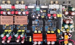
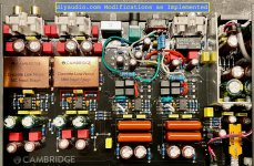
I am adding the PCB layout for reference (before my current changes).
— I guess C75 being 0.5‰ of C21, it has no meaningful impact on the transition frequency.
I am adding the PCB layout for reference (before my current changes).
Attachments
Yes, f = 1/(2*PI*R*C). Close enough given component tolerances, if 1265 is a value you have handy.So RC = R45 X C21 = 1265Ω X 40nF ==> 3145Hz?
I think I will replace R45 with 2200Ω for 9.5cm/s (1800Hz pole), then parallel that with 3kΩ for 19cm/s over a switch. That adds up to 1269Ω, close enough.
No, but it may have an impact on stability, which is what it's there for originally. Such caps are placed close to the opamp to prevent trace inductance from interfering with their purpose. That's why even if it looks like it's doing nothing being in parallel with a much larger capacitance, I'd leave it be.— I guess C75 being 0.5‰ of C21, it has no meaningful impact on the transition frequency.
That is exactly the case. Poles go up or down, zeros go flat (or at least flatter), with increasing frequency.the curve is going up or down after the pole or flattening to a zero.
The terminology derives from the mathematics concerned.Is that just shorthand for people who really understand electronics or should it in fact be indicated in same manner?
Hi, I have another question on a different but related matter, if I may.
I just fixed this rather rare — and totally obsolete — Grundig “DC International-type cassette” player for cars, from 1966. It is meant to work with a matching radio — when a cassette is played, the radio audio is interrupted and instead the tape preamp output is sent to the power amp in the radio.
My question — primarily because I am ignorant of these earlier transistor designs — is why they have used an output transformer? The transformer measures as 1:1, so I assumed it is not for voltage gain. It is also not, presumably, driving a low impedance load?
If I wanted to bypass that transformer, can I just attach a capacitor to one leg of the input side? Should / could I also disconnect the transformer and replace it with a like value (315Ω) resistor.
The output signal is on the low side but perfectly acceptable. In my trials I connected the transformer output directly to a “today’s” power amp, skipping the original cable and the potentiometer.
I would appreciate any feedback and all the best,
Ali Elam
Attachments
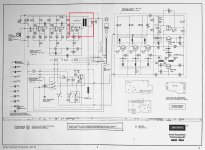
Galvanic separation, the output is floating. The unit can work either with + or - on the cars ground (switch KS2).

Thank you! So it has nothing to do with impedance matching or amplification but for floating the output with respect to ground, B+ and so forth. Can I not eliminate it if I stick to simply (-) ground?Galvanic separation, the output is floating. The unit can work either with + or - on the cars ground (switch KS2).
Whoever owned or installed this before, took out the voltage conversion bar (KS1, not needed for 12V) and broke the outside tip of the polarity changer, KS2, so it cannot be accessed without removing the enclosure.
Thank you again.
If I disconnect the trafo and replace it with a 315ohm resistor, is there a risk I may burn the last transistor? Does it need to see an inductor?
I am sorry for my ignorance of these transistor design matters!
I am sorry for my ignorance of these transistor design matters!
The dc operating point of the transistor T3 does not depend much of the collector resistor. So, with 330 ohm it should work fine from a dc POV.
Thank you, I will.
This is a nicely made, high quality machine. Once I figured out voltage and polarity, it worked immediately. Even the motor belt was in good shape.
(Of course from a practical point of view it is completely useless, being stillborn even in its day. But if we do not preserve gadgets of the past [even the mistakes], who will?)
Take good care of the motor. Replacement is unobtainium. Don't know if the motor from Uher Report series fit.
So far I only added a drop of synthetic clock oil.
The real question (!) for me is...do I mount a stereo head...change the amplifier...record tapes on a cassette player after first adjusting for the 5.08/4.75cm speed difference on Audacity...swap the tape from the CC to the DC..!
I have seven DC cassettes. Not many on offer. Maybe I can 3D print some!
So be committed to yourself and do not modify it. There are enough old car compact cassette players around to use.But if we do not preserve gadgets of the past [even the mistakes], who will?
True. Plus in a (particularly 1965 convertible) car environment who is going to distinguish between stereo and mono…
- Home
- Source & Line
- Analogue Source
- Question about tape equalization preamp