Here you go.
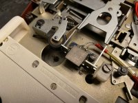
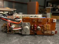
The only modification I made is remove the worn DIN connector and replace it with a female 3.5mm jack for sound and a “today’s” 12VDC power connector. Mechanically, it works perfectly.
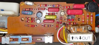
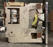
Sound output very is low. Touching either end of the head cable produces no interference. Yet touching the casing of T1 or T2 produces a very loud ruckus. That makes me wonder if C3 is faulty.
The only modification I made is remove the worn DIN connector and replace it with a female 3.5mm jack for sound and a “today’s” 12VDC power connector. Mechanically, it works perfectly.
Sound output very is low. Touching either end of the head cable produces no interference. Yet touching the casing of T1 or T2 produces a very loud ruckus. That makes me wonder if C3 is faulty.
Attachments
-
 7ba27407-76f1-4454-bdb1-6735d3f46d25.jpeg318.5 KB · Views: 48
 -
 5eda1cfb-890e-49ac-a056-9270cf82ee0d.jpeg255.5 KB · Views: 51
 -
 a18667e9-3e41-4827-99c6-22def6e4e865.jpeg360 KB · Views: 44
 -
 ef1cd151-8b2d-4e41-988d-e9b64ab62700.jpeg188.3 KB · Views: 51
 -
 417524f5-02ea-4967-b1cc-93612c5fbb76.jpeg181.7 KB · Views: 51
 -
 655d3f89-a047-43dd-ad84-100650befe4f.jpeg225.5 KB · Views: 46
 -
 1f993a4d-c124-4d51-a16c-86e6746eb502.jpeg164.7 KB · Views: 49

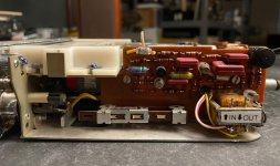
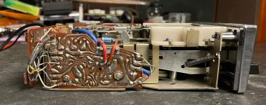
Honestly, this does not even feel like a 1960s “West German” device — soldering job is poor, one capacitor (blue Valvo) is soldered on the back of the PCB as an afterthought. Check out the hole that the black wire goes through: it breaks a PCB trace, which is then reconnected with a short length of red wire. I wonder if they knew this format was failing and they just produced a small number of car units without much planning.
Attachments
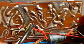
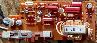
Incidentally, this was the most fruitful “recapping” ever. The output went up some 10X. One 25μF I replaced measured 22nF, another, 100μF, measured 1μF!. I also replaced much of the cabling which was too short and tight with amateurish solder joints.
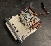
I used new polymer capacitors and was able to relocate two remote-located electrolytics onto the PCB, as they are much smaller. Unfortunately I cannot find multi-value kits of “through hole” polymer capacitors. These are all SMDs, for which I made “legs” from discarded resistor leads. Takes some extra time.
I used new polymer capacitors and was able to relocate two remote-located electrolytics onto the PCB, as they are much smaller. Unfortunately I cannot find multi-value kits of “through hole” polymer capacitors. These are all SMDs, for which I made “legs” from discarded resistor leads. Takes some extra time.