It is silly to have a 10,000% over-margin on current and 4% over-margin on voltage.requires a 52V diodes. ...snip.... I don't think you need a 10A rectifiers but it's cheap insurance.

It apparently depends on the name of the person and the choice to calculate with software what is silly or not 🙂
Mark,The simulated transformer accepts 240VRMS and provides 18VRMS as shown.
Thanks for taking the time to do this but IMHO, I don't think the simulation is correct because the diode bridge is being fed by two 18 Vrms secondaries which are wired and phased in series so, the voltage across the bridge is 36 Vrms. Then the simulated diode PIV would double to 50.4V which is over the limit. Right?
Attachments
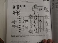
Yikes, yer exactly right!! I erroneously "saw" those eight components C14-C17 + D3-D6 on the left, as eight diodes. I.e. two bridges of four diodes each. I also erroneously interpreted the two 18VAC connectors, as completely independent secondaries. One secondary per four-diode bridge. But what I "saw" was wrong! There are only four diodes, and there is only one rectifier bridge, and the transformer secondaries are not independent, they are connected in a Center Tapped arrangement.
Which means my simulation circuit was certainly NOT what Douglas Self drew, and so my simulation results are irrelevant & worthless for this thread.
Very sorry for the error, thank you for pointing it out. Commence vituperation as you see fit!
Which means my simulation circuit was certainly NOT what Douglas Self drew, and so my simulation results are irrelevant & worthless for this thread.
Very sorry for the error, thank you for pointing it out. Commence vituperation as you see fit!
No problem, and yes, I do think that section of the schematic is a little too busy for good comprehension.
Yup. This is when I figured out that with an 850VCT transformer, I needed to put three UF5408 in series for them not to fail... Now, my amplifiers use lower voltages so a single HER*08 will do it...I made the same mistake before in a tube amp, kept popping the rectifier diodes and i couldnt figure out why. Finally realised i had close to 800v reverse voltage on a 600v rated part. I can also say from experience that power transformers make some angry noises when the diodes fail 😆
UPDATE: I replaced the MBR1045 diodes with MBR1060. The diodes now are operating at about 28 C. Thanks for all the suggestions. It was helpful and I learned several things.
Thanks for the update - it's good to hear it worked out well.UPDATE: I replaced the MBR1045 diodes with MBR1060. The diodes now are operating at about 28 C. Thanks for all the suggestions. It was helpful and I learned several things.
Ah good to hear it is solved. Maybe it is good idea to drop an email to Elektor as there will likely be other builders experiencing the same in the years of using that device and some won't notice the heat or they will replace the parts for exactly the same when it breaks down. There was a time I enjoyed reading Elektor and they used to have an "erratum" page with notification and correction of design errors. I thought D. Self is a member here, maybe he is the best point of contact. It is a device from 10 years ago but still....
https://www.elektormagazine.com/pages/Contact-us
https://www.elektormagazine.com/pages/Contact-us
Last edited:
Mark, did you take into account that when the diode is cut off, with -25V peak at one side, the other side is at the rectified voltage, ~+25V? Total ~50V across the diode?Another hypothesis is that Douglas Self is correct and you gentlemen are wrong. LTSPICE agrees with this second hypothesis. According to LTSPICE, the peak reverse voltage seen by any of the four diodes in the bridge is -25.2 volts . . . . . which is comfortably below the -45 volt Absolute Maximum Rating of the MBR1045 diode whose datasheet is attached to post #9 of this thread. There's nothing wrong with Douglas Self's design. There's something wrong with your analysis of it.
I asked LTSPICE to simulate one of the two transformer secondaries and one of the two diode bridges -- the one that provides the positive DC output. Schematic and .asc file below.
The simulated transformer accepts 240VRMS and provides 18VRMS as shown.
The (positive) output is +24V DC with a peak-to-trough ripple of about 1V. Load current is thus (24V / 150R) = 0.16 amperes.
Anode-to-cathode voltage of diode D1 varies between +0.45V (diode Vfwd) and -25.2 volts.
You are welcome.
_
Edit - I now see it has been resolved.
Jan
What about the 4700uF 35V cap before the regulators?
Is 35V enough or it needs, as the diodes, a higher rating?
Is 35V enough or it needs, as the diodes, a higher rating?
The caps need Vpeak. The rectifiers may need twice Vpeak.Is 35V enough
The power supply from the Linear Audio preamp article, that shares the same structure and part numbers on the diodes and transformer seems to have the same issue. I believe this one is also a Self design but not sure.

Is it the same transformer? (Not that it matters-- we can never find the exact same part.)part numbers on the diodes and transformer
https://media.digikey.com/pdf/Data Sheets/AlfaMag Elect PDFs/L01_Series.pdf
15 VA Part Number = Secondary, No load voltage, Resistance 20°C
L01-6354 ==== 2 x18V, 417mA 2 x22.2V, 2 x5.3ohm
There's not 400mA here, so nearly no-load. 22.2VAC makes 32V peak. The diode can see almost that much extra in reverse, so wants 63V PIV. The part is specified 115V primary and I have 125V sometimes, so 68V PIV. 35V first caps will work today, even 30-day warranty, but may burst in a decade. (I have done worse and got paid.)
Early in my career I had mixed feelings about rectifiers. They failed a lot because of cost and poor design choices. OTOH replacing rectifiers was (part of) my day-job and easy money. Now that nobody pays me to replace rects, my feeling is to double the stress, and double again if I can afford it. So 136V or 272V? If 1N400x parts were fashionable, in small lots they are all the same price to 600V then a penny more, so I'd only buy 1N4007 (1,000V). Schottkys cost more but 200V 20A parts are in-stock at under a buck each. Or SUR1560 DIODE SCHOTTKY 600V 15Amp, 4,113 In Stock, 1 : $0.65 .... yeah, "obsolete" but at that price a hundred costs less than a good birthday lunch and will last longer.
Hello, can someone explain what is the point of using very fast diodes in rectifiers for mains frequency? Thank you
tks for the master class PRR🙂
I am trying to layout the schematic and send it to jlpcb, as a way to learn automatic assembly, just for personal use.
I am trying to layout the schematic and send it to jlpcb, as a way to learn automatic assembly, just for personal use.
There is not one. Standard rectifiers will work perfectly well.Hello, can someone explain what is the point of using very fast diodes in rectifiers for mains frequency? Thank you
18 volts rectified makes 25V, but why then double it? Voltage rating for the caps is not 50V....?So, over 50.9V peak, 45V rated diode. That's why they die.
The maximum reverse voltage is twice the peak voltage. Peak of 18V is 25.45V. Twice that is 50.9V.
(snipped)
The peak voltage of 18V RMS is about 25V, and the diode must block the NEGATIVE 25V peak from the POSITIVE 25V on the capacitor, a total of 50V across the diode.
Schottky diodes are fast and have a low forward voltage which makes them suitable for low voltage, high frequency SMPS, but they are not suitable for higher voltage and 50/60Hz power supplies.
Schottky diodes are fast and have a low forward voltage which makes them suitable for low voltage, high frequency SMPS, but they are not suitable for higher voltage and 50/60Hz power supplies.
- Home
- Amplifiers
- Power Supplies
- Question about power supply rectifiers heating