It seems mister Self is also human and makes mistakes like many others (read ALL of us) also do.
What is the actual power consumption? It seems a 10A Schottky diode is somewhat overrated with regards to current ratings. If actual current is way below 5A the SB580 comes to mind. Not TO220 but fits usually. Slightly higher Uf though but that does not seem a real issue here. The heat seems to be caused by breakdown not the average load current. SB5xx diodes are easy to find. FWIW I use SB540 and SB560 often and they're OK.
What is the actual power consumption? It seems a 10A Schottky diode is somewhat overrated with regards to current ratings. If actual current is way below 5A the SB580 comes to mind. Not TO220 but fits usually. Slightly higher Uf though but that does not seem a real issue here. The heat seems to be caused by breakdown not the average load current. SB5xx diodes are easy to find. FWIW I use SB540 and SB560 often and they're OK.
Last edited:
Sure looks like a mistake - but could be my interpretation of something he said. I was using the book "Self on Audio"So you guys are saying that the original article written by Douglas Self, which calls for a 2x18VAC transformer and MBR1045 rectifiers (image in post #1 of this thread), contains a glaring error?
BTW the MBR10100 (10A, 100V, Schottky) is in stock at lots of distributors today, according to (octopart.com)
I'm not sure of actual power consumption but the recommended fuse for 120V is 600mA so i'd guess a 10A diode is overrated in that regard.It seems mister Self is also human and makes mistakes like many others (read ALL of us) also do.
What is the actual power consumption? It seems a 10A Schottky diode is somewhat overrated with regards to current ratings. If actual current is way below 5A the SB580 comes to mind. Not TO220 but fits usually. Slightly higher Uf though but that does not seem a real issue here. The heat seems to be caused by breakdown not the average load current. SB5xx diodes are easy to find. FWIW I use SB540 and SB560 often and they're OK.
Post #1 contains the original schematic with the design imperfection isn't it? You could drop him an email asking what he thinks about this.
Do you happen to know the actual current the PSU delivers? Is somewhat of a key parameter. You can be very sure by inserting that DMM. Once in the "+" and once in the "-". The mains fuse does not say enough. Actual mains current is way lower, also lower than 50VA as no one loads a transformer 100%. Let's do an assumption here for a change 🙂 Let's say it's around 25VA so 50% of the maximum power as somewhat usual in healthy engineering. With 2 x 18V AC that would be 0.7A. Even with 50VA load we talk about less than 1.5A. This makes the choice for a 45V 10A rated Schottky diode questionable in 2 aspects.
There seems to be more choice in lighter rated Schottky diodes. If it really need to be TO220 diodes I think I would use MUR860 (non Schottky) as that one is in many DIYers drawers. Why was a Schottky chosen at all?
Last edited:
You need to account for line voltage variation too. It's 120V +/- 5% which is 114V - 126V, and it can sometimes go higher.I suppose that I could also change to a 15V transformer. That would give me peak reverse voltage of 42.43V.
My neighborhood went up to 130V, which made all kinds of trouble before I reported it. Caused by bad capacitor banks according to the repair crew.
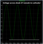
Another hypothesis is that Douglas Self is correct and you gentlemen are wrong. LTSPICE agrees with this second hypothesis. According to LTSPICE, the peak reverse voltage seen by any of the four diodes in the bridge is -25.2 volts . . . . . which is comfortably below the -45 volt Absolute Maximum Rating of the MBR1045 diode whose datasheet is attached to post #9 of this thread. There's nothing wrong with Douglas Self's design. There's something wrong with your analysis of it.
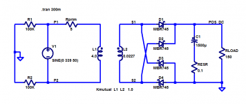
I asked LTSPICE to simulate one of the two transformer secondaries and one of the two diode bridges -- the one that provides the positive DC output. Schematic and .asc file below.
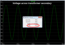
The simulated transformer accepts 240VRMS and provides 18VRMS as shown.
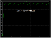
The (positive) output is +24V DC with a peak-to-trough ripple of about 1V. Load current is thus (24V / 150R) = 0.16 amperes.
Anode-to-cathode voltage of diode D1 varies between +0.45V (diode Vfwd) and -25.2 volts.
You are welcome.
_
I asked LTSPICE to simulate one of the two transformer secondaries and one of the two diode bridges -- the one that provides the positive DC output. Schematic and .asc file below.
The simulated transformer accepts 240VRMS and provides 18VRMS as shown.
The (positive) output is +24V DC with a peak-to-trough ripple of about 1V. Load current is thus (24V / 150R) = 0.16 amperes.
Anode-to-cathode voltage of diode D1 varies between +0.45V (diode Vfwd) and -25.2 volts.
You are welcome.
_
Attachments
Yes, Post 1 is photo of the schematic from his book - the one I used to build. Excellent idea to drop him an email. I believe he is back answering emails (wasn't for a while).Post #1 contains the original schematic containing the design imperfection isn't it? You could drop him an email asking what he thinks about this.
Do you happen to know the actual current the PSU delivers? Is somewhat of a key parameter. You can be very sure by inserting that DMM. Once in the "+" and once in the "-". The mains fuse does not say enough. Actual mains current is way lower, also lower than 50VA as no one loads a transformer 100%. Let's do an assumption here for a change 🙂 Lets say it's around 25VA so 50% of the maximum power as usual in healthy engineering. With 2 x 18V AC that would be 0.7A.
I don't know the actual power consumption of the preamp. It does have many opamps and probably a dozen relays. I'm leaving town for a couple days but will measure current when I return. In the interim I'll send Doug an email.
I'm no expert on this but the way the transformer secondaries are connected, I think the diodes are getting 36VAC. Two 18V secondaries connected in series with center connected to ground. To me it looks effectively like a 36V center tap transformer. If that's correct then diode bridge is getting 50.9 V reverse voltage. But, as I say, I'm only a novice.
If all would be fine the diodes would not go kaputt. Simple. I learned to calculate with Graetz diode bridges in combination with center tapped transformers just like PRR does and don't do any simulation. IF one simulates stuff then it would seem handy to enter the double secondary winding/center tapped circuit as used in reality.
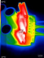
When you would know the current and it is below 1A then things will be more clear. Schottky diodes don't heat up to 80 degrees Celsius surface temp with less than 1A flowing when things are like they should be but all premature conclusions with regards to the current.
When you would know the current and it is below 1A then things will be more clear. Schottky diodes don't heat up to 80 degrees Celsius surface temp with less than 1A flowing when things are like they should be but all premature conclusions with regards to the current.
Last edited:
OIC. SPICE's diodes are perfectly matched and two per half-cycle split the reverse 50V exactly. My rule o' thump assumes one diode may take all the voltage. Neither idealization is true. 1N4007 parts tend to leak a bit before breakdown so the semi-match assumption is more true.LTSPICE agrees with this second hypothesis.

Hirscwi, the diodes see nominal -51Vpk PIV as described by others, so a 45V PIV rated diode is not an appropriate part to use. Are you able to get MBR1060 parts, as they should have been the design parts, and are equivalent in all operational ways to the MBR1045 ? You can then do an operating temperature comparison to confirm the higher temp was related to excessive leakage around peak inverse voltage.
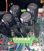
It doesn't look like the pcb would allow sensing current on each of the regulator feeds. If you were keen to do that then you could lift the input leg of each regulator and insert say a 1 ohm current sense resistor that you can probe to confirm current is nominal, and not at a raised level (heatsinks may mask the temp rise if the current was moderately higher than expected).
It doesn't look like the pcb would allow sensing current on each of the regulator feeds. If you were keen to do that then you could lift the input leg of each regulator and insert say a 1 ohm current sense resistor that you can probe to confirm current is nominal, and not at a raised level (heatsinks may mask the temp rise if the current was moderately higher than expected).
As I wanted to know I looked through my old books and the rule of thumb I found even says to choose at least twice the calculated value of PIV per diode. Reasons are mentioned to be safety and non idealities/tolerances of parts. The LTSPICE pilots probably don't have this rule of thumb in the calculations so we probably end up in a "computer says NO" situation..My rule o' thump assumes one diode may take all the voltage.
Funny thing is that to encourage "worst case" calculation and to memorize it it was called "worst-kaas" principle from the English "worst case" (datasheets were in English only). So the sausage-cheese principle.
MBR1045 simply was a wrong choice. One can debate as much a possible but fact is that they become hot and die in a pretty normal situation with a relatively low load. They are followed by relatively small filter caps and a 7815 + LM317 and a lM337 at the negative side. No extreme inrush currents and maximum 2.5A on the positive side and 1.5A at the negative side. Even the famous audio designers at diyaudio.com hopefully don't design for maximum load. That is way under their current ratings so what is left as a reason?
Last edited:
I have ordered the MBR1060 diodes (60V reverse), but even those don't seem to have quite enough safety margin. I should have ordered the MBR10100 diodes, which are 100V reverse voltage. DigiKey has a bunch of these so I'll order a few of those also. Since I have the 1060s coming I'll try them to see if heat reduced.
I really appreciate the discussion on this. I've learned a lot during the discussion and that's the most fun part of this hobby.
I really appreciate the discussion on this. I've learned a lot during the discussion and that's the most fun part of this hobby.
As others have indicated, with the small load of a pre-amp the diodes should be operating at close to room temperature.
The high temp is explained by the fact that during break down the diode has full reverse voltage across it (like a zener diode) and even a small current pulse will cause fairly large power to be dissipated. For example, lets say it breaks down at 50V with a 100 mA pulse, then the power dissipation during the pulse is 5 W. Yes, the pulse is short but it repeats at 60 Hz or maybe 120 Hz, so the heat builds up. The actual breakdown current pulse will be much higher since there is little series resistance to limit it.
The high temp is explained by the fact that during break down the diode has full reverse voltage across it (like a zener diode) and even a small current pulse will cause fairly large power to be dissipated. For example, lets say it breaks down at 50V with a 100 mA pulse, then the power dissipation during the pulse is 5 W. Yes, the pulse is short but it repeats at 60 Hz or maybe 120 Hz, so the heat builds up. The actual breakdown current pulse will be much higher since there is little series resistance to limit it.
The peak voltage on a rectifier is 2.83 times the RMS voltage so a 18V transformer requires a 52V diodes. So the transformer is fine but the diodes are not. I don't think you need a 10A rectifiers but it's cheap insurance. I would use 1N5401 which are not Schottky, but the audiophiles may not agree. In any case, it is the use for low voltage Schottky diodes that is the root of your troubles.
Regular diodes and snubber on the transformer secondaries - use Mark Johnson's Quasimodo to determine snubber component values.
Mark would have kept the MBR1045 diodes 🙂
What is not done is simple voltage measurements (besides the also not carried out current measurements). That are normally the first measurements one would do when a problem occurs. That 2 x 18V transformer is putting out higher output voltage with light loads so actual average, peak voltage and peak to peak voltage (they seem to get mixed up....) will be higher in reality.
What is not done is simple voltage measurements (besides the also not carried out current measurements). That are normally the first measurements one would do when a problem occurs. That 2 x 18V transformer is putting out higher output voltage with light loads so actual average, peak voltage and peak to peak voltage (they seem to get mixed up....) will be higher in reality.
Last edited:
Here is the complete text for the right context, the right device, the right part and the right subject.Another hypothesis is that Douglas Self is correct and you gentlemen are wrong. LTSPICE agrees with this second hypothesis. According to LTSPICE, the peak reverse voltage seen by any of the four diodes in the bridge is -25.2 volts . . . . . which is comfortably below the -45 volt Absolute Maximum Rating of the MBR1045 diode whose datasheet is attached to post #9 of this thread. There's nothing wrong with Douglas Self's design. There's something wrong with your analysis of it.
I asked LTSPICE to simulate one of the two transformer secondaries and one of the two diode bridges -- the one that provides the positive DC output. Schematic and .asc file below.
The simulated transformer accepts 240VRMS and provides 18VRMS as shown.
The (positive) output is +24V DC with a peak-to-trough ripple of about 1V. Load current is thus (24V / 150R) = 0.16 amperes.
Anode-to-cathode voltage of diode D1 varies between +0.45V (diode Vfwd) and -25.2 volts.
You are welcome.
_
Last edited:
- Home
- Amplifiers
- Power Supplies
- Question about power supply rectifiers heating