If i may refer you to my latest project: Post in thread 'Small+Loud+Light BT Speaker Build' https://www.diyaudio.com/community/threads/small-loud-light-bt-speaker-build.426612/post-8006948
Both the 56 & 36 to lack power. At some point ill integrate multiple different scalable rails onto one board mixing the 23 and 56.
What you basically want is an idle power comsumption of 0. Efficiency for 100W+ is not as crucial. For this, the actual mosfet gate charge and drive level of the internal H-Bridges play a big role. With 3 parallel ICs, its like 5W of idle power draw difference. And that matters alot
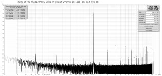
The first set of measurements includes the FFT spectrum of the amplifier with the power supply disconnected, the FFT of the operating amplifier with the inverting input of the OPA862 shorted to ground, and time-domain waveforms in response to a square wave excitation. For the oscillograms, the measurement point is located upstream of the filter preceding the QA-403 audio analyzer.
FFT measurement of the amplifier with supply voltage removed:

FFT analysis of the operating amplifier with the inverting input of the OPA862 shorted to ground:

Oscillogram of the amplifier's response to a 5 kHz / 50% duty cycle square wave into an 8-ohm resistive load:

Square wave response (5 kHz, 50% duty) with external load disconnected; 2.2 kΩ resistor remains at output:

FFT measurement of the amplifier with supply voltage removed:
FFT analysis of the operating amplifier with the inverting input of the OPA862 shorted to ground:
Oscillogram of the amplifier's response to a 5 kHz / 50% duty cycle square wave into an 8-ohm resistive load:
Square wave response (5 kHz, 50% duty) with external load disconnected; 2.2 kΩ resistor remains at output:
This measurement series was performed with the tube preamplifier stage bypassed, focusing on the TPA3126 amplifier section with the PFF (Post-Filter Feedback) loop and the phase inverter based on the OPA862. An RC low-pass filter (3.9 kΩ + 470 nF) is placed in front of the phase inverter input.
Frequency reponse:

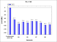
FFT spectrum at an output power of approximately 1 W:


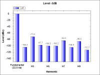
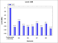
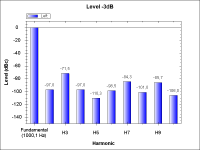
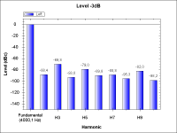
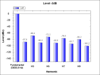
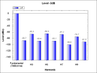
FFT spectrum at signal level -3dB:


Multitone test at an output power of approximately 1 W:

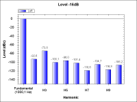
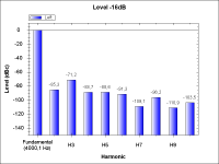
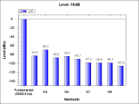
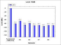
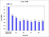
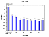
Multitone test at signal level -16dB:

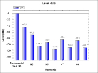
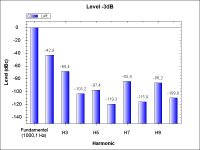
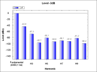
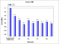
Multitone test at signal level -3dB:

Frequency reponse:
FFT spectrum at an output power of approximately 1 W:
FFT spectrum at signal level -3dB:
Multitone test at an output power of approximately 1 W:
Multitone test at signal level -16dB:
Multitone test at signal level -3dB:
THD measurement series of the TPA3126 stage (PFF loop + OPA862 phase inverter), with the tube preamp bypassed.
Attachments
-
 NoTubePreamp-THD_1W_22Hz.png17.2 KB · Views: 92
 -
 NoTubePreamp-THD_1W_125Hz.png17.3 KB · Views: 98
 -
 NoTubePreamp-THD_1W_1kHz.png17.2 KB · Views: 90
 -
 NoTubePreamp-THD_1W_4kHz.png17.6 KB · Views: 94
 -
 NoTubePreamp-THD_1W_5.66kHz.png17.7 KB · Views: 90
 -
 NoTubePreamp-THD_1W_8kHz.png17.8 KB · Views: 94
 -
 NoTubePreamp-THD_-16dB_22Hz.png17.6 KB · Views: 94
 -
 NoTubePreamp-THD_-16dB_125Hz.png17.5 KB · Views: 96
 -
 NoTubePreamp-THD_-16dB_1kHz.png17.8 KB · Views: 94
 -
 NoTubePreamp-THD_-16dB_4kHz.png17.8 KB · Views: 97
 -
 NoTubePreamp-THD_-16dB_5.66kHz.png17.9 KB · Views: 88
 -
 NoTubePreamp-THD_-16dB_8kHz.png17.9 KB · Views: 94
 -
 NoTubePreamp-THD_-3dB_22Hz.png18 KB · Views: 94
 -
 NoTubePreamp-THD_-3dB_125Hz.png18.1 KB · Views: 93
 -
 NoTubePreamp-THD_-3dB_1kHz.png18 KB · Views: 89
 -
 NoTubePreamp-THD_-3dB_4kHz.png18.1 KB · Views: 91
 -
 NoTubePreamp-THD_-3dB_5.66kHz.png18.3 KB · Views: 93
 -
 NoTubePreamp-THD_-3dB_8kHz.png18.5 KB · Views: 96
For comparision my 1W/8R TPA3118 measurement shows significant higher H3 distortion than your latest plot.
So I think there is nothing left to improve further THD.
So I think there is nothing left to improve further THD.
Attachments
Last edited:

The last two test sets evaluate the full amplifier chain with the tube preamp stage, starting with frequency response, FFT, and multitone analysis.
Frequency reponse:

FFT spectrum at an output power of approximately 1 W:


FFT spectrum at signal level -3dB:


Multitone test at an output power of approximately 1 W:

Multitone test at signal level -16dB:

Multitone test at signal level -3dB:

Frequency reponse:
FFT spectrum at an output power of approximately 1 W:
FFT spectrum at signal level -3dB:
Multitone test at an output power of approximately 1 W:
Multitone test at signal level -16dB:
Multitone test at signal level -3dB:
THD measurements of the complete amplifier including the tube preamplifier stage.
Attachments
-
 WithTube-THD_1W_22Hz.png17.7 KB · Views: 91
 -
 WithTube-THD_1W_125Hz.png17.8 KB · Views: 91
 -
 WithTube-THD_1W_1kHz.png17.8 KB · Views: 90
 -
 WithTube-THD_1W_4kHz.png17.9 KB · Views: 88
 -
 WithTube-THD_1W_5.66kHz.png17.9 KB · Views: 89
 -
 WithTube-THD_1W_8kHz.png17.9 KB · Views: 90
 -
 WithTube-THD_-16dB_22Hz.png17.8 KB · Views: 94
 -
 WithTube-THD_-16dB_125Hz.png17.8 KB · Views: 96
 -
 WithTube-THD_-16dB_1kHz.png17.7 KB · Views: 92
 -
 WithTube-THD_-16dB_4kHz.png17.8 KB · Views: 90
 -
 WithTube-THD_-16dB_5.66kHz.png17.9 KB · Views: 86
 -
 WithTube-THD_-16dB_8kHz.png18 KB · Views: 90
 -
 WithTube-THD_-3dB_22Hz.png18.2 KB · Views: 91
 -
 WithTube-THD_-3dB_125Hz.png18.2 KB · Views: 93
 -
 WithTube-THD_-3dB_1kHz.png18.2 KB · Views: 91
 -
 WithTube-THD_-3dB_4kHz.png18.1 KB · Views: 89
 -
 WithTube-THD_-3dB_5.66kHz.png18.2 KB · Views: 91
 -
 WithTube-THD_-3dB_8kHz.png18.4 KB · Views: 96
In the tube stage, the capacitance of the capacitor between the anode and ground should be reduced. A slight peaking in the frequency response should be observable in the measurement. This will help avoid excessive bandwidth limitation when the load exhibits low resistance and inductance in the range of approximately 30 µH — the worst-case scenario observed in simulations.
The square wave response is, in my opinion, excellent — even when the only load is the 2.2 kΩ resistor mounted on the PCB.
A particularly interesting result is the THD at 1 kHz and approximately 1 W output power, which measures 0.0037% — five times lower (corresponding to the PFF loop depth) than the 0.02% specified in the TPA3126 datasheet.
For signal levels of -16 dB and -3 dB, the measured THD values are 0.021% and 0.022%, respectively. Unfortunately, there is an increase in the third harmonic at -16 dB input level, where I would have expected a lower overall THD — particularly for the -3 dB condition, which I anticipated to yield at least 50% lower distortion.
Well, what remains for me is to further optimize the values of the PFF loop components through simulation to slightly reduce the frequency response dependency for different RL load combinations and to modify the operating point of the tube stage. I might consider using the MAX5440 with an encoder as a replacement for the potentiometer at the amplifier input. As a second option, I'm considering a version with more classic tubes like the EF95, plus a magic eye EM87 as a visual attractor.
--> saniiiii
The only thing that changed was a different filter between the amplifier output and the load, and the measurement analyzer. The second change was a different amplifier power supply—a budget-friendly switching converter, let's say. Below is the schematic of the load, voltage divider, and filter. The resistors are cermet types—those 33-ohm ones are rated at 20W, and the remaining 47-ohm ones are also cermet but rated at 5W. The inductors are vertical THT chokes. The capacitors are film types: the 22nF one is metallized polypropylene, while the 47nF one is metallized polyester.

This improvised block consisting of the load, voltage divider, and filter is, of course, far from ideal. The cermet resistors are not non-inductive. These vertical chokes have cores with significant magnetic field dispersion. Despite the compact build, the whole setup is still quite large and unfortunately acts as a "nest" of antennas. The coils should ideally have ferroxcube cores, but those are only available in SMD format, not THT. The whole assembly should be shielded, but with ventilation to allow heat dissipation.
The worst part is the lack of proper non-inductive power resistors. On "paper," it looks good—cutoff frequency around 180kHz, and at a switching frequency of 1200kHz, we have attenuation no worse than 40dB. But that’s just "on paper," because in reality, both the chokes and cermet resistors effectively behave like parasitic RF transformers. The oscilloscope showed the same residual switching frequency at both the input and output.
Additionally, in the building where I live (a residential block built in the mid-1970s), there is no power installation with a protective earth conductor. Since I live on the 7th floor, grounding is simply not an option.
What’s my point? That even though the switching frequency is far above the 192kHz sampling rate, its remnants still show up in the FFT spectrum within the measured frequency range. Hence those two initial measurements. I’m fully aware this is far from proper metrology. However, these measurements are only meant to validate the simulation results. In my opinion, I achieved what I aimed for, and I believe the simulation results of the frequency response are sufficiently close to what the real amplifier produces.
One more thing I'd like to add. I understand the statement that these measurements “look better.” OK—I know where the issue lies: it's in the initial tube stage, and for people who are unfamiliar with vacuum tubes and their characteristics, this might affect their judgment. That’s why I conducted a separate measurement series that bypasses the tube stage. (I didn’t need this personally, since for me, the 5th and higher harmonics characterize the TPA circuit with the PFF loop well enough; I interpret the 2nd and 3rd harmonics differently.)
I also added a relevant oscilloscope capture of the amplifier's response to a square wave signal, even though the slight “ringing” is not significant for music playback. There are no square impulses in music. Besides, the music source itself has a limited bandwidth, and the audio cables also contribute some low-pass filtering. Let's also not forget the limited bandwidth of the tube preamp stage. All of this makes it unlikely that such waveforms would even reach the power stage with PFF.
The only thing that changed was a different filter between the amplifier output and the load, and the measurement analyzer. The second change was a different amplifier power supply—a budget-friendly switching converter, let's say. Below is the schematic of the load, voltage divider, and filter. The resistors are cermet types—those 33-ohm ones are rated at 20W, and the remaining 47-ohm ones are also cermet but rated at 5W. The inductors are vertical THT chokes. The capacitors are film types: the 22nF one is metallized polypropylene, while the 47nF one is metallized polyester.
This improvised block consisting of the load, voltage divider, and filter is, of course, far from ideal. The cermet resistors are not non-inductive. These vertical chokes have cores with significant magnetic field dispersion. Despite the compact build, the whole setup is still quite large and unfortunately acts as a "nest" of antennas. The coils should ideally have ferroxcube cores, but those are only available in SMD format, not THT. The whole assembly should be shielded, but with ventilation to allow heat dissipation.
The worst part is the lack of proper non-inductive power resistors. On "paper," it looks good—cutoff frequency around 180kHz, and at a switching frequency of 1200kHz, we have attenuation no worse than 40dB. But that’s just "on paper," because in reality, both the chokes and cermet resistors effectively behave like parasitic RF transformers. The oscilloscope showed the same residual switching frequency at both the input and output.
Additionally, in the building where I live (a residential block built in the mid-1970s), there is no power installation with a protective earth conductor. Since I live on the 7th floor, grounding is simply not an option.
What’s my point? That even though the switching frequency is far above the 192kHz sampling rate, its remnants still show up in the FFT spectrum within the measured frequency range. Hence those two initial measurements. I’m fully aware this is far from proper metrology. However, these measurements are only meant to validate the simulation results. In my opinion, I achieved what I aimed for, and I believe the simulation results of the frequency response are sufficiently close to what the real amplifier produces.
One more thing I'd like to add. I understand the statement that these measurements “look better.” OK—I know where the issue lies: it's in the initial tube stage, and for people who are unfamiliar with vacuum tubes and their characteristics, this might affect their judgment. That’s why I conducted a separate measurement series that bypasses the tube stage. (I didn’t need this personally, since for me, the 5th and higher harmonics characterize the TPA circuit with the PFF loop well enough; I interpret the 2nd and 3rd harmonics differently.)
I also added a relevant oscilloscope capture of the amplifier's response to a square wave signal, even though the slight “ringing” is not significant for music playback. There are no square impulses in music. Besides, the music source itself has a limited bandwidth, and the audio cables also contribute some low-pass filtering. Let's also not forget the limited bandwidth of the tube preamp stage. All of this makes it unlikely that such waveforms would even reach the power stage with PFF.
For comparision my 1W/8R TPA3118 measurement shows significant higher H3 distortion than your latest plot.
So I think there is nothing left to improve further THD.
I’m not familiar with the detailed implementation of your PFF (Post-Filter Feedback) loop, particularly its depth, but a noteworthy aspect is that your design is based on the TPA3118. This IC, along with the TPA3116, represents an older generation compared to the more recent TPA3126 and TPA3156 devices. According to the respective datasheets—specifically the THD vs. output power characteristics—this earlier generation exhibits approximately 6 dB higher total harmonic distortion at 1 kHz and 1 W output compared to the updated TPA3126 and TPA3156 variants, which feature improved internal modulation and error correction mechanisms.
Therefore, the inferior measurement performance you've observed (as you yourself noted) is not unexpected. Additionally, it’s worth mentioning that the choice of FFT windowing function can also impact the measured result by several dB. In my case, the Hann window is used, which provides a good balance between frequency resolution and spectral leakage suppression, but still introduces a certain trade-off in amplitude accuracy.
Yes, TPA3118 is not the actual bleeding edge of technology,
but quite good value for money.
My PFFB does not improve audio THD or noise figure but improves exclusively square wave response.
As long as my THD-measurements outperform the EVA-kit everything is fine for me.
The real culprit are output inductors, TI has shown an eye-opening comparison table of THD figures with various inductors.
I object to carbonyl cores - they distort excessively and to air cores as well - inacceptable copper losses and stray field.
Some Sendust toroids are not too bad.
For me gapped ferrite cores are the way to go. The bigger the better.
Do not use MLCC in the audio path including LC output filter.
Any arbitrary film caps are fine.
There have been rumors with THD increasing load resistors that I cannot confirm,
but sometimes a got increased distortion due to contact problems in the output circuit.
The importance of square wave response is debatable -
considering the fact that our digitized music implies a sharp amplitude roll-off above 20kHz.
From this point of view you can generate a square wave using the soundcard and REW or similar SW as a reference signal.
This will output a band limited square wave that will not excite resonant peaks above 20kHz.
Also the input LP-Filter of the amp contributes to flattening the sharp square wave edges.
With this real-world filtering your overshoots will disappear more or less completely.
Being a beast of an engineer, I skip all these filters and test the worst case scenario
with real sharp square waves
However - the real world relevance is debatable.
Last edited:
Regarding MLCC capacitors, let's clarify. Indeed, X7R and other dielectrics of class 2—that is, ferroelectric and ferrielectric types—present the problem of strong capacitance dependence on voltage (and a possibly less significant issue like the piezoelectric effect). However, for relatively small capacitance values, C0G (NP0), which is a class 0 dielectric, can still be offered. A compromise is the U2J (N750) dielectric, class 1, which shows a decrease in capacitance with increasing temperature but no capacitance dependence on voltage.
MLCC capacitors feature very low ESR values, meaning negligible losses. For filters in this class, if anything, I would use larger sizes like 1812 or 2220. Among film capacitors, metallized polyester types are preferable. Texas Instruments especially recommends capacitors with dV/dt ≥ 100 V/μs for higher power applications.
Here lies a problem because the MK2 series (and also MKS2, but that's a different topic), characterized by a small footprint (5 mm lead spacing), is only offered by WIMA. Kemet is out, and Epcos has similar parts but with a much larger footprint. Unfortunately, availability issues affect both WIMA and Epcos.
This applies not only to signal capacitors but also to decoupling capacitors, which deserve close attention. Why? Because certain universal laws always apply: the same current flowing at the output will flow through the power supply (input current is negligible). Some tend to underestimate this, but the power supply does not have zero impedance.
I used TPA3126 power supply decoupling consisting of: 2 × 2.2 nF C0G + 2 × 100 nF X7R + 6 × 680 μF polymer organic aluminum capacitors. These MLCCs are placed under a heatsink right next to the IC.
I am considering replacing the two pairs of ceramic capacitors—2.2 nF + 100 nF (each 0805)—with a single 100 nF capacitor but of C0G or U2J type (1206).
That covers capacitors, especially ceramic ones, since the dielectric type is often ignored.
Finally, resistors and the THD they introduce. This is a problem because the resistivity of the resistor material decreases with increasing voltage. This particularly affects "ordinary" resistors. Metallized MELF resistors are better in this regard (from older times I fondly remember Soviet-made MLT resistors, though their silver-plated leads become problematic after years due to silver sulfide).
Sometimes, precision thin-film resistor datasheets include graphs of THD versus voltage.
No. Besides ESR linearity considerations of decoupling caps are moot.This applies not only to signal capacitors but also to decoupling capacitors,
You really do not need big COG or any film caps for decoupling purpose,
considering the potential of TPAxxxx this is pure over-engineering imho.
Power decoupling caps are selected for low ESR.
AC current is high, AC-voltage low.
MLCC or Low ESR electrolytics are fine here.
Low ESR MLCC on the other hand are the worst choice in output filter -
high AC voltage and accordingly high dieelectric losses and distortion.
Last edited:
Besides our beloved red Wimas there are other options buying film caps.
Have a look at MKT2 types, for instance.
Available 1uF pitch 5mm - no problem.
look for Kemet
Have a look at MKT2 types, for instance.
Available 1uF pitch 5mm - no problem.
look for Kemet
Last edited:
Higher power applications like offline LLC-converters with full ac voltage swing - yes.Texas Instruments especially recommends capacitors with dV/dt ≥ 100 V/μs for higher power applications.
Class-d output filter with AC voltage in the ballpark of 1Vpp - no
Last edited:
However, in the documentation regarding reconstruction filters for devices such as the TPA3244/TPA3245, Texas Instruments specifically recommends that if a film capacitor is used in the output filter, it should have a rated voltage of at least 100 V and a minimum dV/dt rating of 100 V/μs.
Practically speaking, only WIMA offers metallized polypropylene capacitors with a 5 mm lead spacing — i.e., a very compact footprint — and this is the MKP2 series. You suggest using Kemet MKT capacitors, but first of all, those are polyester film types, which unfortunately have a dV/dt rating dozens of times lower than a polypropylene capacitor rated for the same working voltage. I’m basing this on WIMA datasheets, where such parameters are clearly specified.
While EPCOS film capacitors (though also increasingly difficult to source) offer similarly detailed specifications — sometimes even more detailed than WIMA — they, unfortunately, lack 5 mm pitch package options in their current lineup.
Back to Kemet: the situation is even worse. In equivalent film series, instead of a multilayer structure, you’re getting a wound construction, which typically results in higher ESR and, more critically, significantly higher ESL.
That said, it's becoming evident that film capacitors like MKS2 and MKP2 will gradually disappear from the market, likely being replaced by ceramic MLCCs. Yes, I understand the concern with dielectric types — since C0G ceramics are limited in both capacitance and voltage ratings. However, stacking MLCCs is a possible workaround.
In the end, MLCCs with C0G or even U2J dielectric types may turn out to be a better alternative than MKP, particularly for compact, low-inductance applications.
I disagree strongly with a requirement of 100V/us for output filter caps.
There is no way to generate transients in that ballpark at the output filter.
ESL adds to series output inductance - so what?
ESR adds to series output resistance - so wat?
Maybe I will do some testing with Kemet RM5
Anyway - analogue circuitry is on the way to obsolescence - whether we like it or not.
Have a look here
https://www.mouser.de/datasheet/2/447/F3294_MMK-3316041.pdf
1uF/MMK5 with a series resonant frequency close to 2MHz
corresponding to about 10nH series inductance
There are better options as well
https://www.mouser.de/datasheet/2/447/KEM_F3101_R82-3316969.pdf
https://www.mouser.de/datasheet/2/447/F3294_MMK-3316041.pdf
1uF/MMK5 with a series resonant frequency close to 2MHz
corresponding to about 10nH series inductance
There are better options as well
https://www.mouser.de/datasheet/2/447/KEM_F3101_R82-3316969.pdf
Last edited:
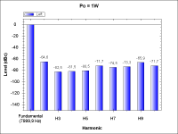
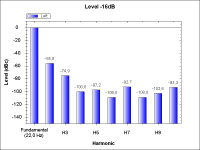
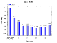
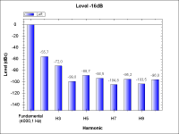
Assuming the same circuit topology, I’m modifying the operating point of the tube stage to increase overall sensitivity — better matching the so-called “consumer level” of -10 dBV, with some headroom. The grid bias resistor at the input of the OPA863 has been increased from 68 kΩ to 220 kΩ. This does not negatively impact the noise floor, since the triode stage (with local negative feedback) has a low output impedance, more than ten times lower than the value of the grid resistor.
In addition to the (possibly excessive) gain, this change improves the harmonic structure of the THD, particularly the distribution and amplitude of higher-order harmonics. I’ve also slightly adjusted values in the RC network.
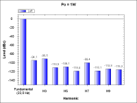
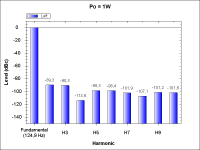
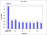
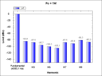
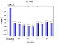
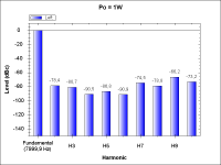
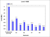
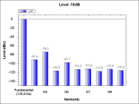
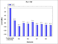
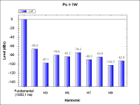
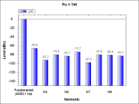
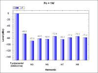
Attached is a set of frequency response plots for various RL combinations (resistive-inductive loads), as well as THD simulation results showing the tube stage's contribution to the 2nd, 3rd, and 4th harmonics.


Po = 1W:

Input level -3dB:

Unfortunately, I’ll need to replace the TPA3126 on my PCB — one channel is dead, and a multimeter shows a short between pins 4 and 5 (RINP and RINN). There's no visible solder bridge on the PCB, and the DC bias voltage on both pins reads a correct 3 V.
There is, admittedly, one mistake on the board layout — a trivial but silly error related to the power connector. I have a spare TPA3116, but not a TPA3126, so I’ll need to order a replacement and acquire a hot-air rework station and Kapton tape for proper installation. Sometimes things just have to get a bit tricky.
In addition to the (possibly excessive) gain, this change improves the harmonic structure of the THD, particularly the distribution and amplitude of higher-order harmonics. I’ve also slightly adjusted values in the RC network.
Attached is a set of frequency response plots for various RL combinations (resistive-inductive loads), as well as THD simulation results showing the tube stage's contribution to the 2nd, 3rd, and 4th harmonics.
Po = 1W:
Input level -3dB:
Unfortunately, I’ll need to replace the TPA3126 on my PCB — one channel is dead, and a multimeter shows a short between pins 4 and 5 (RINP and RINN). There's no visible solder bridge on the PCB, and the DC bias voltage on both pins reads a correct 3 V.
There is, admittedly, one mistake on the board layout — a trivial but silly error related to the power connector. I have a spare TPA3116, but not a TPA3126, so I’ll need to order a replacement and acquire a hot-air rework station and Kapton tape for proper installation. Sometimes things just have to get a bit tricky.
Last edited:
- Home
- Amplifiers
- Class D
- Question about optimizing PFFB for TPA3245