BTW, the pot is linear.
So if R7 is fully clockwise then the inverted input (pin 6) gets the full R signal and pin 5 is open. If CCW, then the opposite.
If the source is a mono signal and the pot is at 12 o'clock I would indeed expect zero output.
But at fully CCW why would "the - input is taken directly to the input source" be a problem? It's as if there's no pot in place, no?
My concern was that the other pin would be floating, i. e., it would be unconnected to anything.
How do I get out of this mess?
You know, a while back I had a simpler version using the ancient LM386. And it worked perfectly! My problem at the time was that I was using a wall wart and had terrible hum. Instead of just addressing that alone I got ambitious.
I don't think that would work. The gain on the inverting input is -R12 divided by whatever resistance is feeding signal into the inverting input and the gain seen by the non inverting input is (R12/R) + 1
In practice that means output signals get very large very quickly when they are anything other than identical.
This is just 10 millivolts of input signal with one channel 180 degrees out of phase.

And this is the opamp output. Over 3 volts peak, gain now of over 300 in this configuration.

The circuit does not break any design rules but its not doing what you wanted I'm afraid 🙁
In practice that means output signals get very large very quickly when they are anything other than identical.
This is just 10 millivolts of input signal with one channel 180 degrees out of phase.
And this is the opamp output. Over 3 volts peak, gain now of over 300 in this configuration.
The circuit does not break any design rules but its not doing what you wanted I'm afraid 🙁
Is it only the size of new resistor R21?
If not, do you have any ideas on how to affect the "voice suppression" section?
If not, do you have any ideas on how to affect the "voice suppression" section?
Its the location of it really. It needs to go in series with the input to the pot so that there is always some resistance present to keep a lid on the gain. Ultimately You probably shouldn;t be swinging the pot to the extremes anyway, there would be no need.Is it only the size of new resistor R21?
You will also find that the input imedance of the two inputs are always goin to be different in a simple configuation like this. The non inverting input sees 200k to ground at all times and so with the pot at 0 ohms it is 200k input impedance and with the pot at 100% it is 200k +250k
The inverting input by nature of the feedback at this point sees an input impedance of 250k with the pot at one extreme and that falls all the way down to zero at the other extreme. That is a downside of a single opamp setup for this.
Have you tried taking actual audio to listen to from the output of the opamp and seeing if you can at least null the voice to some extent. If the voices are central in imaging then you should be able to get some kind of reduction or null.
Years ago it was popular to connect a rear speaker (or two series connected speakers) between the amplifier + outputs to get a kind of surround sound ambience effect. Anything central in the stereo image (vocals) would not come through as both + outputs had similar content and so the speaker sees no signal related to that. The left and right differences would come through.
Mouly, I thought I'd posted #86. Do you think this would at least stop the terrible overloading?
It would help up to a point.
You could try something like this which gives a null when the pot is centred and will allow you to turn the pot fully each way without it going unstable but you will still reach a point where it will clip the signal at high level... but... you should need to be turning the pot to those extremes. If you can't remove vocals with it near the centre point then it will be because the recording is going to have to much separation between channels of the vocals.
You could try something like this which gives a null when the pot is centred and will allow you to turn the pot fully each way without it going unstable but you will still reach a point where it will clip the signal at high level... but... you should need to be turning the pot to those extremes. If you can't remove vocals with it near the centre point then it will be because the recording is going to have to much separation between channels of the vocals.
Attachments
Mouly, for the life of me I tried - and I trust your recommendations - but I cannot see why the 10K resistors are there.
That is, once I've changed over from that grounding scheme to the current one it seems to me that:
at full CCW - we expect 100% of the L channel and zero of the right - the inverted (R) input (pin 6) still has a 250K resistance (from the pot) between it and the 4.7uF cap. The same, albeit inverted for the non-inverted (pin 5), is true at full CW.
Why, then, would I need the 10K resistor in series before the pot?
The 10k stops the opamp inverting input from being pulled right down to what could be effectively a 'ground' condition. In that situation the gain would be off the scale and the opamp would lose the ability to maintain its DC conditions. The output could latch to a rail.
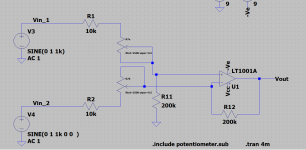
The circuit reduces to this. One side of the pot at 250k and the other at zero ohms. V4 is set for 'no signal' and presents as a low impedance to ground (as would many source components). V3voltage is just 10 mv here and that is enough to drive the opamp into clipping. A real world opamp at this point would latch to a rail as the DC feedback could not establish.

The circuit reduces to this. One side of the pot at 250k and the other at zero ohms. V4 is set for 'no signal' and presents as a low impedance to ground (as would many source components). V3voltage is just 10 mv here and that is enough to drive the opamp into clipping. A real world opamp at this point would latch to a rail as the DC feedback could not establish.

Whoops . . . I meant 'Mooly.' In fact, I apologize because to a Scot 'mouly' means cheap.
I do understand what we're trying to prevent.
I have attached the current circuit.
The R7b wiper is connected to pin 3. As such when at extreme CCW the resistance into the IC1b inverting pin (6) is 250K, no?
When in the extreme CW position the pot is shunted and the inverting input is connected to the Right input through C3.
But you believe that a 10K resistor is necessary to prevent the IC from going nuts. So I must not understand how the pot/IC config works.
By "The output could latch to a rail" do you mean it would be effectively at ground state?
Attachments
With a real opamp the output state is unpredictable and would be opamp dependent which way the voltage went.By "The output could latch to a rail" do you mean it would be effectively at ground state?
Although its a real enough problem I wouldn't get to hung up on that aspect at this point. You should be working with the pot around the midpoint for most situations and the first thing to do is just to configure and prove that the concept works to null the vocals. Remember it will only null information common to both inputs with regard to their amplitude and phase.
- Home
- Source & Line
- Analog Line Level
- Question about Ground of an IC