They can go either way around because they see zero DC voltage across them using the opamps shown. If the applied source has a DC offset then that will appear across the caps at a value that depends on the pot settings but there is still no right and wrong way to fit them without knowing if such a condition exists (and it shouldn't)
Well . . . the neon pilot light works . . . but none of the three functions works.
A mono line output was inserted into J1 and J2.
"Zero" pots (R1 and R2) were brought all of the way up.
Headset volume (R19) was brought all of the way up.
The U2 internal volume control was brought nearly all of the way clockwise.
The selector (SW2) was set to CC (Center Channel) and the CC volume pot (R6) was brought half way up.
There was barely a detectable sound. I didn't think the total inline resistances would suppress the (likely) 0.5 volt input so heavily.
Then I switched SW2 to "D-" which is the voice suppression circuit.
When R7ab was at 12 o'clock there was nothing. But when I panned to the left I started to get a very loud squeal!
What the hell am I overloading?
Switching to "D+" (the inverse of "D-") I got nothing.
While I could hear only a very low sound it seemed that the low pass section was doing what it's supposed to do.
If I had any hair I'd have pulled it all out.
(I also noticed that when I inserted those line inputs from my stereo unit into J1 and J2 the stereo's speaker volume dropped.)
Attachments
You need to trace the signal through with an oscilloscope to see what is going on. Apply a sine wave at 1kHz to each input and follow its progress through the circuit. The circuit as drawn does not seem to break any rules and each subsection should certainly work... but tracing the signal will show where it is going wrong.
It is also worth checking the output pin of each opamp is as zero volts DC.
It is also worth checking the output pin of each opamp is as zero volts DC.
That depends on the output impedance of the source. The loading is 10k in parallel with 25k (R1 and R3) with R4 and R6 also contributing. So its going to be around 6k depending on the pot settings.(I also noticed that when I inserted those line inputs from my stereo unit into J1 and J2 the stereo's speaker volume dropped.)
i can pick up a sig. generator and oscilloscope cheaply enough but while i know what to do with the former you'll have to tell me what i'm looking for on the scope.
i'm also going to rerun my continuity/discontinuity checks - what should be connected is, and what better not be isn't - as well as measuring the DC voltage of pins 1 and 7 on the three ICs. There are caps connected to three of the four opamp outputs. I measure at the pin, right? The cap would block DC, no?
i'm also going to rerun my continuity/discontinuity checks - what should be connected is, and what better not be isn't - as well as measuring the DC voltage of pins 1 and 7 on the three ICs. There are caps connected to three of the four opamp outputs. I measure at the pin, right? The cap would block DC, no?
Yes, you measure the DC voltage at the output pins.
You won't be overdriving it but if the Onkyo has an output impedance of say 2.2k and you load it with 6k then you cut the signal level down a lot. 1 volt output would fall to around 0.7 volts when loaded in that way.
The oscilloscope is just a voltmeter that traces out voltage against time and so lets you see the signal in real time.
As a side note . . .
1. I use shielded coax for the connections up to ICs 1 and 2. I also use twisted pairs for the runs between J1/J2 and J3/J4 and J10.
I figured it'd cut down on 60-cycle hum. Am I mistaken?
2. I count on there being a slight gain from ICs 1 and 2. Again, am I mistaken?
1. I use shielded coax for the connections up to ICs 1 and 2. I also use twisted pairs for the runs between J1/J2 and J3/J4 and J10.
I figured it'd cut down on 60-cycle hum. Am I mistaken?
2. I count on there being a slight gain from ICs 1 and 2. Again, am I mistaken?
Shielded cable will cut down on stray hum pickup but its all pretty low impedance circuitry in the scheme of things and so not very prone to that.
One thing I have spotted is that R7B wiper can be taken all the way down to ground potential if fully turned and that would cause the gain of IC1b to go off the scale. That could be the reason for th squeal you heard.
If that control is just a 'balance' or 'trim' then you would not normally go anywhere near that region as the control would be in the central part of its range.
Good catch!
But the R7 balance is meant to be able to swing fully CW and CCW.
I want to be able to feed the "D-" (IC1b) input with "just left" or "just right" so as to pick out different components of each channel.
How can I fix this?
And when R7 is almost at full CCW there is about 0.1V DC from pin 7, its output. (It varies with how far CCW I go.)
The "center channel" portion (IC1a) is unaffected by anything I do, as is IC2. IC3 has a barely noticeable DC voltage (pin 1).
But with all of this the volume is soooo low (other than the damn squeal). Are the R1, R2 and R3 values too low?
I cannot remember why I chose 22K for the L+R mix (R4, R5) but it seems to be satisfactory in that it shouldn't "corrupt" the incoming signal.
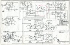
Mouly, I've attached the AR integrated amp (circa 1968) schematic so you can see where my madness began.
The unit has a three-position selector ring around the balance pot. The choices are "Stereo," "Mono" and "Null."
The third position was fascinating to me at the time, as well as necessary. One used that feature when adjusting the phono input pots on the back panel to adjust for the stylus tracking differences (as well as the possible RIAA pre-amp differences). The key, of course, was to use a mono record. But when applied to a stereo source you often found that the voice was attenuated well enough so that you hear more clearly the instruments. I want to provide that feature. And I include a center channel section so that I can combine them in an opamp thus producing a voice-only output. It's a simple enough idea . . . you'd think.
Attachments
Never load an op amp with less resistance than stated as minimum in the data sheet.
This is typically 2k, but some are as low as 600R.
You are talking of the resistor to ground at the output (often shown 1k or 2K) ? Or is the preamp next stage is enough with its 25>K to 100K input ?
On the datasheet, is it not to say it is the minimal load the output should see in the planned design (so to show the minimal value your next stage or device should have as input resitance ?
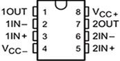
I've attached the LF353P data sheet. I do not see any reference to user input resistance or impedance expectation.
(And, yes, typical inputs are 600R to ~2K.)
There is though a note about the inordinately high (10y12) internal input resistance. I must be missing something.
I'm afraid I'm lost when you speak of "the resistor to ground at the output." Please refer to specific resistors (or components) by designation.
There is no "pre-amp next stage." What did you have in mind?
Attachments
How's this for R7ab?
Its proving more problematic I suspect than it first appeared. Electrically its fine...
This is with identical inputs applied. Vin1 and Vin 2 are superimposed on each other being the same. There is no output voltage. Pot at midpoint. Input voltage is 1 volt peak.
45 degree phase shift applied to Vin 2
Pot at 20% still with 45 degree phase shift applied.
Pot near 0% rotation. Clipping of output. This all becomes more pronounced as the phase shift between inputs increases and will be worst with 180 degree shift as here.
Pot at 100% and 180 degree phase shift.
With no phase shift (mono) and pot on 100% all three superimpose. The output equals the input.
I'm not sure if this is even what you want it to do. Should the connections to one pot be reversed so as one goes up the other does down?
First, I thank you for all of the time you've clearly put into this.
R7 is a balance pot. That is, one goes up as the other goes down. And I believe I have configured this correctly . . .
On the Left: when at CCW (L) the wiper connects to pin 3 which is the left input. At full CW it connects to pin 1 which is itself.
My concern here, apropos a previous recommendation of yours about not leaving the unused amp unconnected, is that I have the wiper connected to nothing but itself. (See what I do with pins 5, 6 and 7 on ICs 2 and 3.) Could this be a problem?
Continuing, so, too, is the deal on the right: when at CCW the wiper connects to pin 3 which is itself. At CW (R) it connects to pin 1 which is the right input.
The R7b wiper connects to in the inverted input (of IC1, amp #2), pin 6. As such it should be 180 degrees out of phase with the R7a connection (pin 5). That’s been at the heart of this project since day 1.
Attachments
Pins 5, 6 and 7 look good. That is one of the recommended ways to deal with unused opamps, connecting it as a buffer with the output floating.
With the pot configured to go up/down you will get zero output from the opamp for a mono input at all settings.
So pot R set at zero ohms in one channel and 250k in the other.

You see the same through the full rotation. Nothing changes in the output for a mono signal.
If the signals are different you get output from the opamp. 45 degree shift and pot at 10% and 90% and then 90% and 0%
(Input remains at 1 volt, the scales change)


Going to 100% and 0% create the 'infinite' gain situation as the - input is taken directly to the input source.
With the pot configured to go up/down you will get zero output from the opamp for a mono input at all settings.
So pot R set at zero ohms in one channel and 250k in the other.
You see the same through the full rotation. Nothing changes in the output for a mono signal.
If the signals are different you get output from the opamp. 45 degree shift and pot at 10% and 90% and then 90% and 0%
(Input remains at 1 volt, the scales change)
Going to 100% and 0% create the 'infinite' gain situation as the - input is taken directly to the input source.
- Home
- Source & Line
- Analog Line Level
- Question about Ground of an IC