Thus the 'simple amps make better sound' is a myth; it is a 'nice' myth and so widely believed but it is completely untrue.
All amps sound very good.
And simple ones and the complex ones.
I like them both and they're equal good sounding, just different pattern.
the quality is the same, just different goodness.
Don't like only when there is an audible distortion but this is in the past.
Last edited:
I do. I think Self does too (especially after he read my articles in Wireless World). The reason is simple: a correctly-biased CFP output provides a reasonably flat transconductance curve across the output currents. Most other output topologies do not.
No. It is a compound follower, which at high currents has an approximately constant transconductance and can be adjusted so that at a certain low quiescent current it has half this transconductance. Nothing like an opamp.
Its both compound follower and an op-amp like the push-pull stages which can be class A or class B.
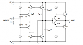
See the first stage from the attachment, then remove the current mirror and attach a normal VAS with resistors for loads.
You will end with 4 transistors, 2 resistors and 2 inputs - inverting and noninverting.
Attach the output of the VAS to the inverting input directly without a divider and then look again to realize this is sziklai xD
yeey it seems that you didn't know that
And this adjustment u talking about is the bias of the op-amp 😀 😀
-----
Aaaand this is why it oscillate sometimes but the cure of rod elliot is not proper because he use only 1 cap and the position is wrong 😀
There must have 2 caps and they must be at the output Qs because as I mentioned this is VAS and need caps to set its gain to 1 @ HF
Attachments
Last edited:
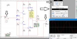
Maybe you didn't know that a push pull VAS stage biased at 50ma can output Amperes current
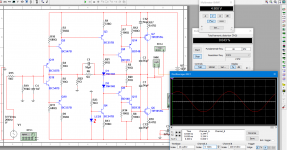
Look the feedback divider which is also 6 ohm load, look at the input voltage, 0.6Vrms, then the output voltage 3.9Vrms, the divider ... 15%,..
and tell me that this is not an operational amplifier.
Look at the THD --> 0.011% and this is only an output stage man !
Imagine what beast is this with an additional input stage which linearizes moore.
----
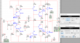
The problem is that the output trans are not fed by EFs and this can be solved by adding one stage which is also a beta enchancer (look the 2nd attachment but I forgot to attach the 6 ohm load)
--------
PS: forgot to bootstrap the example, It lowers THD veeery much
Look the feedback divider which is also 6 ohm load, look at the input voltage, 0.6Vrms, then the output voltage 3.9Vrms, the divider ... 15%,..
and tell me that this is not an operational amplifier.
Look at the THD --> 0.011% and this is only an output stage man !
Imagine what beast is this with an additional input stage which linearizes moore.
----
The problem is that the output trans are not fed by EFs and this can be solved by adding one stage which is also a beta enchancer (look the 2nd attachment but I forgot to attach the 6 ohm load)
--------
PS: forgot to bootstrap the example, It lowers THD veeery much
Attachments
Last edited:
Take a skeleton opamp circuit, make several changes to it and then you get something which looks vaguely like a CFP. This is not evidence that a CFP is an opamp.darkshy said:See the first stage from the attachment, then remove the current mirror and attach a normal VAS with resistors for loads.
You will end with 4 transistors, 2 resistors and 2 inputs - inverting and noninverting.
Attach the output of the VAS to the inverting input directly without a divider and then look again to realize this is sziklai xD
yeey it seems that you didn't know that
Irrelevant.darkshy said:Maybe you didn't know that a push pull VAS stage biased at 50ma can output Amperes current
Maybe your definition of opamp is any circuit to which feedback can be applied?darkshy said:Look the feedback divider which is also 6 ohm load, look at the input voltage, 0.6Vrms, then the output voltage 3.9Vrms, the divider ... 15%,..
and tell me that this is not an operational amplifier.
This thread is getting a long way away from a discussion about what constitutes a Class B output.
Which is a fine queue for me to chime in and say: What a wonderful discussion. It certainly made me understand some topics better with some spice added for entertainment.This thread is getting a long way away from a discussion about what constitutes a Class B output.
I've seen several attachments with simulations and simulated scopes and measurements. While I just love the facility of being able to simulate ideas and schematics without the boring step of soldering and the risks of releasing the white smoke, I am curious as to how reliable these simulations can be. Obviously as accurate as each model for each component or variant thereof. I suspect the simulations can give you the broad picture and save you from short circuits and oscilations but are they accurate enough to discriminate between a 0.1% distortion and a 0.05% one? And are they able to consider power dissipation, thermal effects to bias diodes and transistors?
It is blue smoke which makes electronics work; let it escape and the thing stops working. White smoke is what makes steam engines work! 😎
Simulations often get distortion wrong, especially when balanced or push-pull circuits are used. This is because all the devices of a given type are identical in simulation. Use simulation as a useful tool, but never fully believe the results.
Simulations often get distortion wrong, especially when balanced or push-pull circuits are used. This is because all the devices of a given type are identical in simulation. Use simulation as a useful tool, but never fully believe the results.
OK, Sasi. When I started to post things on this thread, I immediately realized that this one would allow a very diverse discussion where "off topics" should be warmly welcomed. 🙂
I haven't learned how to quote properly, here is my version:
" Thus the 'simple amps make better sound' is a myth; it is a 'nice' myth and so widely believed but it is completely untrue."
When we are expressing something we believe in but can't really prove, then it's not a good thing to formulate oneself so that one may be mistaken for a god. For example the phrase "I think it is completely untrue" is a better one ( I think ).
Darkshy:
You like every amplifier? You should be lucky. I think it's extremely challenging to get it right sonically. That's why I prefer simple circuits.
But if we compare a "Honeybadger" and a First Watt amp, I think they have different strengths. The first has probably a very controlled and clear sound and should impress people who appreciate that kind of exhibitionism.
The First Watt has a more intimate sound stage probably and will present the ambience and timbres in a more vivid and stimulating way. Good for jazz for example.
I got some objections when I said that building a perfect amp is simple. Well it is, if we just bias the thing enough. But then it would be a heat moster and our apartments have to have an airconditioner and it would be quite big and expensive. Not a good way.
OK, adding THD masks the clinical sound? Perhaps, but the clinical sound came from using too much NFB and complexity. So a simple and nice amp doesn't have to mask anything, it's just the bad ones that needs that.
One more thing. Some complex amps really sounds quite good. But they will have to be carefully voiced. I think that since it's the THD pattern that sets the sound, tweaking is even more important on complex amps. Probably our brain is more confused by some patterns and finds other less harmful.
Second order is very simple. Digital noise is very complex and disturbing. But white noise ( which is a distortion that it's so complex that it doesn't really have a pattern ( more statistical ) ) is really not disturbing at all. Who doesn't like a bit of noise and cracks!
Some said: Nobody following Self would regard an amp as "perfect". Is Self some sort of deity? He is the god of objectivists. I think the only things he contributed with is the analysis of the biasing of BJT class AB, and the coining of the terrible phrase "blameless". Where is the passion?
"I'm sitting here in front of my stereo and I'm so happy since I really know that my amp can't sound any better".
No, Douglas Self has to be slaughtered! 😀 Some zen monks used to say " If you will meet the Buddha, kill him ! "
http://www.diyaudio.com/forums/forum-problems/304036-quote-function.htmlI haven't learned how to quote properly, here is my version:
So when in post 49 you saidSvitjod said:" Thus the 'simple amps make better sound' is a myth; it is a 'nice' myth and so widely believed but it is completely untrue."
When we are expressing something we believe in but can't really prove, then it's not a good thing to formulate oneself so that one may be mistaken for a god. For example the phrase "I think it is completely untrue" is a better one ( I think ).
what you actually meant to say was "I think simple amps give a simple distortion pattern", otherwise we might think you were claiming deity?Svitjod said:Simple amps gives a simple distortion pattern.
If adding some THD can undo 'clinical' sound then Occam's Razor tells us that 'clinical' sound does not have something nasty in it but distorted sound has something pleasant in it. Adding further distortion to sound which is already distorted will make the distortion more complicated (mathematical fact) so if complex distortion sounds bad then more complex distortion should sound worse. No, the truth of the matter is that many people prefer a little distortion so if it is missing due to well-engineered equipment they often like to add it via a 'tube buffer'.OK, adding THD masks the clinical sound? Perhaps, but the clinical sound came from using too much NFB and complexity. So a simple and nice amp doesn't have to mask anything, it's just the bad ones that needs that.
I realise that masking plays a role, but the correct engineering solution to the presence of a little distortion is not to add a lot more distortion in order to mask it but to reduce the original distortion to below audibility. This works fine provided that less distortion means more pleasant sound; unfortunately this is not true for all listeners.
No, white noise isn't complex distortion. I don't.But white noise ( which is a distortion that it's so complex that it doesn't really have a pattern ( more statistical ) ) is really not disturbing at all. Who doesn't like a bit of noise and cracks!
No. No.Is Self some sort of deity? He is the god of objectivists.
He makes well-attested engineering statements which help people think, if thinking is what they wish to do. If you want poetry instead then you would be better off reading what other 'designers' say.
In listening to well-reproduced music?Where is the passion?
Yes.OK, adding THD masks the clinical sound? Perhaps, but the clinical sound came from using too much NFB and complexity. So a simple and nice amp doesn't have to mask anything, it's just the bad ones that needs that.
Beautiful city, Gothenburg.
Take a skeleton opamp circuit, make several changes to it and then you get something which looks vaguely like a CFP. This is not evidence that a CFP is an opamp.
Maybe your definition of opamp is any circuit to which feedback can be applied?
Yes, any circuit to which feedback can be applied is op-amp.
no, "operational amplifier" was defined specifically for analog computers
before transistors "op amp" was already known as a gain block with standardized input and output properties that make it suitable for simulating mathematical functions/equations
this has typically meant high Z Voltage differential measuring inputs and a low Z Voltage output with high enough gain to to make accurate math functions implemented with the feedback components
you can apply feedback to one or a few tubes or transistors and make useful amplifiers - but amp circuits <~3-4 active devices typically don't have all of the desired properties to be called "op amps"
Last edited:
Sasi - about simulation.
I usually do 98% of the development in the simulator. I simulate, then I listen and then back to sim again, and so forth.
Amplifiers usually are a quite easy chew for a simulator. You cannot get real accuracy with sims, but who needs to know whether an amp has 0.001 or 0.003% THD? The THD is more like sticking up your finger to see where the wind blows.
Sometimes when I'm uncertain I use to make simple comparisons between reality and simulation, and it's surprising how close the reality often manages to emulate the simulation.
When it comes to phase measurements I'm unsure of the accuracy but it's probably satisfying. I hope so since you will need quite advanced equipment to measure such things. Since I prefer simple circuits, the stability usually is of no concern.
I have given up the quoting issue. I will never learn how to do. But generally people quote too much, at least some of them.
Finally about simulators. Recently I used a class AB BJT stage in a high Z state. That is current driven. So I wondered how accurate my simulator was regarding this. It really has to simulate how the hfe varied with current and I had my doubts.
After some while I couldn't resist making some tests. They showed that the simulator was right withing some 50% or so. That may sound much, but all I wanted to know was a rough estimation of the cross over distortion and the THD.
So if I got 0.01% then it might be 0.02% or 0.005%. Who cares?
You cannot get real accuracy with sims, but who needs to know whether an amp has 0.001 or 0.003% THD? The THD is more like sticking up your finger to see where the wind blows.
Sometimes when I'm uncertain I use to make simple comparisons between reality and simulation, and it's surprising how close the reality often manages to emulate the simulation.
..
Since I prefer simple circuits, the stability usually is of no concern.
..
So if I got 0.01% then it might be 0.02% or 0.005%. Who cares?
Yes, I think the same way.
Simulation and reality are not the same but they are very close.
About the stability, I think that the problem comes only from the VAS stage when its gain is high and when driven from a high impedance stage.
Strangely, but I the oscillation comes from RF. It comes from the air and the VAS catches it. Very strange.
Im going to develop a non-oscillating, stable design with no Miller cap or with a cap but a very small one -> 10-15p.
You just need maxed current stage to drive and keep tight the VAS and to found out the max value of the VAS's emitter resistor/s at which the THD satisfy your taste and also the max output swing which is limited with high emitter R.
Last edited:
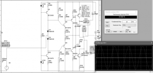
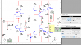
Like this one.
Supply voltage: +-12V
Offset: 200mV
OPS bias current: 300 pA
THD: 0.040% at 20k
Squares: perfect!
The feedback divider is that low because Im using it as load in the simulation.
C1 is not for compensation, this circuit has compensation only at the output transistors because they are VAS too and have very high voltage gain.
This is the better LTP. Im going to build it but using a CCS+Bootstrap bombination. *combination.
Attachments

Last edited:
I am curious as to how reliable these simulations can be. Obviously as accurate as each model for each component or variant thereof.
Look post #12 here
http://www.diyaudio.com/forums/soli...re-current-right-collector-2.html#post5032284
It shows that different transistors can behave the same if you use a high enough emitter resistors.
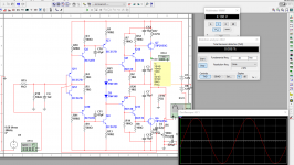
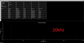
I made some modification and the harmonics pattern is very beautyful.
Notice that the 2nd one shows the both driving-biasing methods and the 1st shows both current gain methods that have only 1 diode drop.(1 is sziklai, 2nd is something like it)
Notice that the 2nd one shows the both driving-biasing methods and the 1st shows both current gain methods that have only 1 diode drop.(1 is sziklai, 2nd is something like it)
Attachments
I made some modification and the harmonics pattern is very beautyful.
Notice that the 2nd one shows the both driving-biasing methods and the 1st shows both current gain methods that have only 1 diode drop.(1 is sziklai, 2nd is something like it)
Someone warned against taking too much out of a simulation. I modelled some favourite circuits recently and the results - 10kHz square wave into 8R with 2u in parallel. All seemed good however I needed to do more work as the .models were not all they were cracked up to be and the circuits failed the test with better .models
It is difficult to have a sensible technical discussion with someone who has private meanings for words. So when you say that the CFP is an opamp, all you meant to say was that the CFP includes local feedback - which is obvious and hardly needs saying.darkshy said:Yes, any circuit to which feedback can be applied is op-amp.
- Status
- Not open for further replies.
- Home
- Amplifiers
- Solid State
- Question about class B output stages