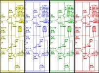
Most of audio discussions about the amplification A, B, AB and C classes concentrate on push-pull configurations. However push-pull output stages are made of two branches which act in parallel when seen by the load.
Each branch can be observed separately and said to be in class A, B, AB or C. This may help a lot for those who have difficulties with the definitions as usually explained.
Borrowed for french Wikipedia ( https://fr.wikipedia.org/wiki/Classes_de_fonctionnement_d%27un_amplificateur_%C3%A9lectronique ) these drawings make things mcuh clearer.
*
a class A amplifier conducts over 100% of the input cycle.

*
a class B amplifier only amplifies 50% precisely of the input wave cycle.
The bias for class B as so defined is impossible to maintain, due to thermal drift and non-linear conduction, the conduction wanders from class AB (more than 50%) to class C (less than 50%). Class B according to this definition is never used.

*
a class AB amplifier amplifies more than 50% of the input cycle.
If the input signal is not too great, the device stays conducting during the whole cycle.

*
a class C amplifies less 50% of the input cycle

*
Push-pull configurations
For push-pull configurations, the output impedance (before overall negative feedback is applied) is an other way to help to characterize the class.
A push-pull class A will have a quite linear output impedance.
In a class AB amplifier, the part of the cycle where both branches are conducting will present a lower impedance than when only one branch is conducting. This effect is sometimes called "gm doubling".
For signals of large amplitudes, the output impedance is not linear. If the signal is of sufficiently low amplitude, the output signal is reproduced as if the amplifier was class A.
Class B now. As the begining of the conduction of an active device is rather smooth, there is a optimal bias settling where the output impedance presents less variations on large signals than in class AB and the signal is less distorded.
As the theorical 50% conduction by branch is practically un-obtainable, the class B definition based on optimal bias is justified.
Douglas Self is not the inventor of this definition. When the first integrated op-amps appear, their output stage was clearly said to be in class B in the data-sheets.
Forget the definition of half cycle conduction for class B.
The imperfect linearity of push-pull class B et AB output stages generates what is often called "crossover distortion". Looking at the very low harmonic distortion of audio ICs shows how optimally biased class B can be linear.
A class C will have a dead zone where a part of the cycle is not transmitted. This is an interesting case because it puts in evidence the importance of the lineraity of the output impedance as the demonstration is done by the power output stage of the Quad Current Dumping amplifier.
It works in class C. So its output impedance is almost infinite when the power devices are not conducting.
However there is an additionnal stage in class A working in parallel, using a combination of negative and feedfoward corrections which exact role of is to maintain the output impedance of the whole circuit the most constant as possible. It is not a class AC but a class A//C.
Each branch can be observed separately and said to be in class A, B, AB or C. This may help a lot for those who have difficulties with the definitions as usually explained.
Borrowed for french Wikipedia ( https://fr.wikipedia.org/wiki/Classes_de_fonctionnement_d%27un_amplificateur_%C3%A9lectronique ) these drawings make things mcuh clearer.
*
a class A amplifier conducts over 100% of the input cycle.
*
a class B amplifier only amplifies 50% precisely of the input wave cycle.
The bias for class B as so defined is impossible to maintain, due to thermal drift and non-linear conduction, the conduction wanders from class AB (more than 50%) to class C (less than 50%). Class B according to this definition is never used.
*
a class AB amplifier amplifies more than 50% of the input cycle.
If the input signal is not too great, the device stays conducting during the whole cycle.
*
a class C amplifies less 50% of the input cycle
*
Push-pull configurations
For push-pull configurations, the output impedance (before overall negative feedback is applied) is an other way to help to characterize the class.
A push-pull class A will have a quite linear output impedance.
In a class AB amplifier, the part of the cycle where both branches are conducting will present a lower impedance than when only one branch is conducting. This effect is sometimes called "gm doubling".
For signals of large amplitudes, the output impedance is not linear. If the signal is of sufficiently low amplitude, the output signal is reproduced as if the amplifier was class A.
Class B now. As the begining of the conduction of an active device is rather smooth, there is a optimal bias settling where the output impedance presents less variations on large signals than in class AB and the signal is less distorded.
As the theorical 50% conduction by branch is practically un-obtainable, the class B definition based on optimal bias is justified.
Douglas Self is not the inventor of this definition. When the first integrated op-amps appear, their output stage was clearly said to be in class B in the data-sheets.
Forget the definition of half cycle conduction for class B.
The imperfect linearity of push-pull class B et AB output stages generates what is often called "crossover distortion". Looking at the very low harmonic distortion of audio ICs shows how optimally biased class B can be linear.
A class C will have a dead zone where a part of the cycle is not transmitted. This is an interesting case because it puts in evidence the importance of the lineraity of the output impedance as the demonstration is done by the power output stage of the Quad Current Dumping amplifier.
It works in class C. So its output impedance is almost infinite when the power devices are not conducting.
However there is an additionnal stage in class A working in parallel, using a combination of negative and feedfoward corrections which exact role of is to maintain the output impedance of the whole circuit the most constant as possible. It is not a class AC but a class A//C.
Last edited:
This 1967 article is also completely in accordance with the definitions used by Self:
Understanding Audio
Of course a bipolar transistor output stage always draws base current, so the distinction between class B1 and class B2 is meaningless for bipolar transistor amplifiers.
Understanding Audio
Of course a bipolar transistor output stage always draws base current, so the distinction between class B1 and class B2 is meaningless for bipolar transistor amplifiers.
DF96, you seem to be in a good mode. The idea that the NOS DAC images may reflect some of the aliasing filtered information is interesting, I will have to ponder that.
Then about tailoring sound by adding benign distortion.
I used to believe that before, but have changed a bit. I don't think THD makes some amps perceived as good sounding. Many minimalistic amps such as tube amps and some of Nelsons designs exhibit somewhat elevated THD figures, but I don't think it's the THD that makes them good. If an amp is designed with low NFB and a made with very few transistors, the harmonic pattern becomes more "simple" and isn't confusing our brains as much, even if the total THD level is higher.
So I would say that THD is rather unrelated to perceived sound quality. But in the best of worlds we would like a very low THD as well.
Actually it's quite easy to build a "perfect" amplifier. Use heavy biased class A stages with no NFB applied and we have a monster. A bit like Krell even if it isn't quite biased enough to give THD figures that matches some of those "super blameless" amps that we can find on this forum.
An easy way to tailor the THD pattern is altering the NFB loop.
Personally, I'm think it's terrifying to have such an amp at home. Regarding the fact that I'm a bit of a subjectivist, I would soon be a nervous wreck trying to find out the most digestible sound.
Then we have the "sweet spot" issue. Usually amps need some tweaking before they start to sing. Thats' why I find Self's work uninteresting. It's all about obvious things that every constructor finds out sooner or later. The risk is that if you build a Selfie-amp, you think it is perfect or at least blameless. But every topology need tweaking. It's the minute nuanses that really makes an amplifier.
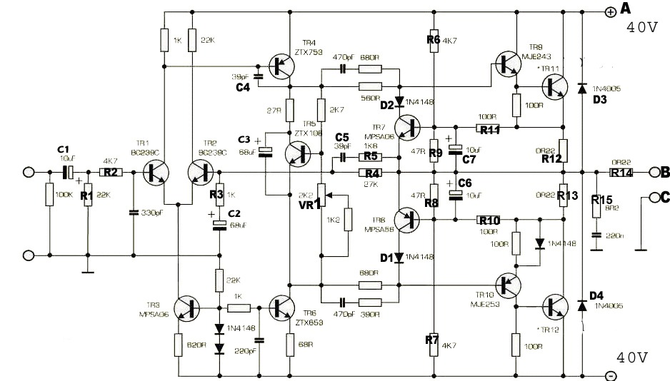
This is a well known Naim amplifier that has a reputation to sound good.
It's more or less a "blameless" amp. But I think it has been carefully listened to during development.
For example, there are some strange things that superficially has no meaning. First the collector resistor of 22k on TR2.
Then we have that strange RC network before the drivers. What purpose of that one? I don't think it has with stability to do since the same phase shift may be accomplished by a resistor in the NFB path.
I suspect this is a typical case of finding a sweet spot.
I've read Self's book, and I understand where he is coming from. He is a set-in-stone objectivist. I think we need both types to further the art. If the objectivist could allow that the goal is to produce enjoyment in a non-perfect human, they might use their highly developed skills to produce a less perfect amplifier that fewer thd analyzers and more people enjoy. If the radical subjectivists could learn some basic engineering, they might begin to see how they are being fleeced by every fad that comes along. On the subject of bias, I would propose that a highly biased class AB design makes a lot of sense. It allows for the vast majority of listening to be done in the class A region, while providing headroom for extreme dynamics, which is much preferred to clipping. If we are talking about mosfets, the output stage is also more thermally stable at a higher bias.
I believe Self is correct about bjts being more linear, and they are a better choice at low bias, but keeping the design in that narrow sweet spot over a wide thermal range isn't easy, and wandering to the underbiased condition leads to a poor sounding amplifier that is thin and harsh.
Sent from my SM-G920V using Tapatalk
That 22k does seem like one of those trial and error in the lab things indeed.
Which RC do you mean, the one with the 470 pFs? I'd think that's for getting a lower drive impedance at high freqs (making the output stage faster and compensating for reduced beta) without affecting thermal compensation.
IMHO much of the traditional "black magic" of audio engineering was about getting a result that sounded as good as possible despite THD figures not being safely filed under "blameless", with the added difficulty of measurement gear being much more modest than what's available today. And yes, distortion spectra, distortion over frequency and level and their relationship to current have got a fair bit to do with that.
except that the DBT listening test evidence suggests that there isn't really any "there", there when it comes to "designing euphonic distortion" into audio power amps for playback (not the same game as instrument amps for musicians)
"linear distortion" == frequency response (which may include the effects of nonzero output Z and "difficult" speaker loads) really seems to be the overwhelming explanation of "amplifier sound"
when of course you actually control for the much larger perceptual effects of loudness, expectation, appearance...
Last edited:
Good point. During blind listening tests the magnitude-frequency responses are usually kept matched within +/- 0.1 dB if the aim is to listen for something else, because some listeners can hear 0.2 dB differences (at least at midrange frequencies, according to a classical article by Lipshitz and Vanderkooy, "The great debate: subjective evaluation"). Many if not most amplifiers have much larger frequency response errors, especially when loaded by a loudspeaker.
Good talking "Nobody". A subjectivist who constantly gets lost in the placebo fumes is quite ridiculous.
Jcx, the thing about amplifier sound. There has been a lot of discussion what it really is. I don't believe in that flat frequency theory. Even if our ears are sensitive, the effect is negligible compared to the rom responses - and we still hear differences.
I have my own home brewed one. Here it comes.
Human hearing is extremely sensitive to patterns. The patterns that comes from subtle reflections and interactions between various sources. It seems to be unknown just how sensitive it is so the usual objectivist argument "therefore it is inaudible at that low level" probably is invalid.
An amplifier creates distortion patterns from all the unlinear stages, that is transistors, etc.. , when these are stacked up in several stages and when a NFB loop makes it even more complicated, yes then we have our famous "sound".
People who have read my other post may think this is my own personal hobbyhorse that I can't let go off. And it is.
The path to audio nirvana is simplicity, it's as simple as that! Simple amps gives a simple distortion pattern. Ask Nelson Pass.
OK, I wont talk about this any more, I will shut my mouth ( at least a while )
This is a well known Naim amplifier that has a reputation to sound good.
It's more or less a "blameless" amp. But I think it has been carefully listened to during development.
For example, there are some strange things that superficially has no meaning. First the collector resistor of 22k on TR2.
Then we have that strange RC network before the drivers. What purpose of that one? I don't think it has with stability to do since the same phase shift may be accomplished by a resistor in the NFB path.
I suspect this is a typical case of finding a sweet spot.
There are a few places where transistor collector loads drop the voltage seen at the collector and generate Miller capacitance. The 22k collector load for Tr2 is a significant one. You can deduce what effect this has on the nfb signal with increasing frequency.
The RC step networks in the driver transistor bases are to match the phase on each side of push-pull halves.
> Most of audio discussions about the amplification A, B, AB and C classes concentrate on push-pull configurations.
This is wrong thinking. As shown in your citation:
"a class B amplifier only amplifies 50% precisely of the input wave cycle."
You look at ONE device and figure how it is working.
Push-pull is something else.
In Audio, Class A will work with one device.
In Audio, Class B will NOT work with one device.
In Audio, Class C will work at all. (Except as a booster to some other amplifier.)
But do not mix-up A/B/C with SE/PP!
In FM/FSK Radio, A B or C can work with ONE device.
AM/SSB will pass through Class A or B.
AM/SSB will NOT work through a Class C stage. (OTOH, a Class C carrier amplifier with audio applied at B+ was the classic AM output stage before cleverer designs were developed.)
I would propose that a highly biased class AB design makes a lot of sense. It allows for the vast majority of listening to be done in the class A region..
+1
What about an output stage with a NFB in it ?
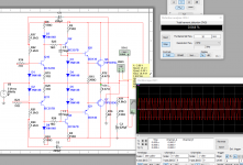
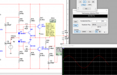
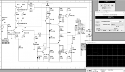
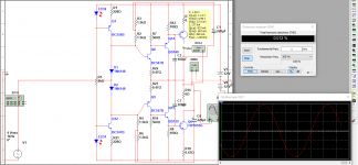
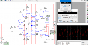
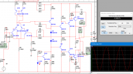
Look at the 1st attachment: No its not a whole amplifier, its only output stage which is monsterous and gives 0.004% @1khz, 0.05% @20k.
It works with the same distortion without bootstrap but its bootstrapped because its little better with it and because I like how bootstrap sounds.
Its biased at only 50ma current.
--------------
Nobody knows why Sziklai sounds better?
I found out why: because its the same thing as this and has NFB in it.
-because the driver transistors form an op-amp with two inverted outputs and the output transistors are the VAS.
Firstly, before this, when the idea came out, I tried this and realized that I reinvented the sziklai but nobody knows its an op-amp with output connected to its inverted in.
I liked it a lot but there was a thing that I didn't like: It was that the drivers weren't emitter followers. Then I came up with the idea for the darlington version.
Summary:
The sziklai gives low THD when bootstrapped.
The darlington version gives it with/without bootstrap.
--------------
> I would propose that a highly biased class AB design makes a lot of sense. It allows for the vast majority of listening to be done in the class A region..
I found out there is a very narrow region that lies us to think this is not true.
In this region higher bias means higher distortion. Also there is regions with almost similar THDs at 1 and 20 khz & regions with very different THDs.
-
Attachments


Last edited:
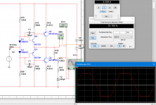
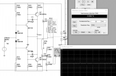
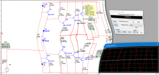
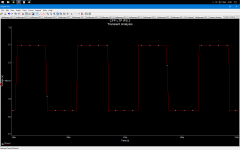
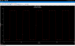
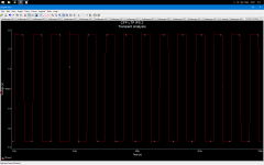
There is error in two of the attachments.
The bias is 800mA in them.
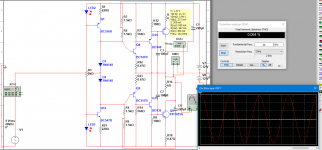
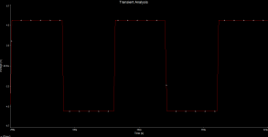
This is the correct one with 256mA bias.
The 2nd attach is with an Input stage to demonstrate the power.
0.009% @ 20khz !
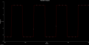
The squares are without the input stage.
The bias is 800mA in them.
This is the correct one with 256mA bias.
The 2nd attach is with an Input stage to demonstrate the power.
0.009% @ 20khz !
The squares are without the input stage.
Attachments
Last edited:
> Most of audio discussions about the amplification A, B, AB and C classes concentrate on push-pull configurations.
This is wrong thinking. As shown in your citation:
"a class B amplifier only amplifies 50% precisely of the input wave cycle."
You look at ONE device and figure how it is working.
Push-pull is something else.
In Audio, Class A will work with one device.
In Audio, Class B will NOT work with one device.
In Audio, Class C will work at all. (Except as a booster to some other amplifier.)
But do not mix-up A/B/C with SE/PP!
In FM/FSK Radio, A B or C can work with ONE device.
AM/SSB will pass through Class A or B.
AM/SSB will NOT work through a Class C stage. (OTOH, a Class C carrier amplifier with audio applied at B+ was the classic AM output stage before cleverer designs were developed.)
Basic electronics defines classes independently of the application. A push-pull configuration for audio is not an exception. There are two branches each being defined as having a class. In most circuits, the class of both is the same.
There is clearly a problem with push-pull class B.
Looking separately at each of its branches helps to understand why the usual definition given for class B "each branch passes half of the cycle" is wrong and where crossover distortion comes from.
Last edited:
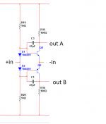
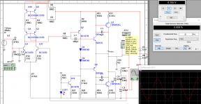
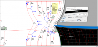
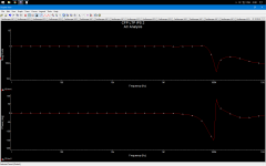
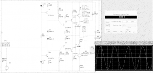
output stage:
- half-bootstraped and half-CCSed OPS.
- 0.008 @ 20khz WITHOUT LOAD
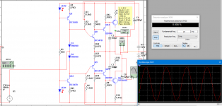
- 0.012% @ 1khz and 6 ohm (7th attachment picture proves this)
- 0.064% @ 20khz and 6 ohm
--
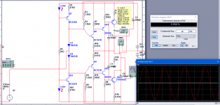
Maybe you think I needed to use 4 bias diodes because it looks like the drivers and the outputs form a darlington but this is not true:
Q8 and Q14 form a sziklai which is equal to a npn transistor with more beta => this npn forms another sziklai with the output one & u need only 2 bias diodes.
Iam explaining again that Q8 and Q9 form an operational amplifier, Q14 and 15 (the drivers) are beta enchancers and outputs are a push-pull VAS.
- half-bootstraped and half-CCSed OPS.
- 0.008 @ 20khz WITHOUT LOAD
- 0.012% @ 1khz and 6 ohm (7th attachment picture proves this)
- 0.064% @ 20khz and 6 ohm
--
Maybe you think I needed to use 4 bias diodes because it looks like the drivers and the outputs form a darlington but this is not true:
Q8 and Q14 form a sziklai which is equal to a npn transistor with more beta => this npn forms another sziklai with the output one & u need only 2 bias diodes.
Iam explaining again that Q8 and Q9 form an operational amplifier, Q14 and 15 (the drivers) are beta enchancers and outputs are a push-pull VAS.
Attachments
-
 149038760674268 (2).png309.3 KB · Views: 63
 -
 149038760674268 (1).png312.8 KB · Views: 66
 -
 149038760674268.jpg119.7 KB · Views: 74
 -
 THE MONSTER IS WAITING (1khz).png75.1 KB · Views: 59
 -
 THE MONSTER IS WAITING (squares3).png38.1 KB · Views: 59
 -
 THE MONSTER IS WAITING (squares2).png42.9 KB · Views: 58
 -
 THE MONSTER IS WAITING (squares1).png59 KB · Views: 55
 -
 THE MONSTER IS WAITING AC.png33.2 KB · Views: 62
 -
 THE MONSTER IS WAITING (WITH LOAD).png79.6 KB · Views: 68
 -
 THE MONSTER IS WAITING.png71.6 KB · Views: 88
Last edited:
Thousands of users of cheap Chinese 'tube buffers' are evidence to the contrary. People find that deliberately (or accidentally) adding some low order distortion to their music makes it sound better to them. There is ample anecdotal evidence that many people prefer moderate levels of low order distortion over lower levels of distortion. Give them sound which has completely inaudible amounts of distortion and they describe it as 'clinical'. In some cases, of course, such people either have never heard live music or actually prefer reproduced music.Svitjod said:Many minimalistic amps such as tube amps and some of Nelsons designs exhibit somewhat elevated THD figures, but I don't think it's the THD that makes them good.
No. It is possible to build a 'blameless' amplifier, but even that is not easy so many people do not attempt it.Actually it's quite easy to build a "perfect" amplifier.
The distortion issues which Self found are not all obvious, and most constructors would never find all of them. Given that some constructors are still struggling with elementary circuit theory issues too! Nobody following Self would regard an amp as "perfect", but he is careful to define "blameless" so that it is achievable. 'Tweaking' a design may be the stage where a blameless circuit has small amounts of distortion reintroduced to meet the particular preferences of the designer.Then we have the "sweet spot" issue. Usually amps need some tweaking before they start to sing. Thats' why I find Self's work uninteresting. It's all about obvious things that every constructor finds out sooner or later. The risk is that if you build a Selfie-amp, you think it is perfect or at least blameless. But every topology need tweaking. It's the minute nuanses that really makes an amplifier.
That could be unbalancing the LTP, thus introducing more common-mode gain and thus common-mode distortion. Or it could be compensating for the rather simple CCS in the tail. It would need careful analysis to tell which is true. In either case, I agree that it is a sign that the amplifier has been at least partly 'designed by ear' and therefore is not intended to be blameless. (Just seen that mjona suggests that it could be modifying the HF feedback via Miller effect - so giving an HF boost to the closed-loop gain i.e. it is a fixed tone control!)For example, there are some strange things that superficially has no meaning. First the collector resistor of 22k on TR2.
My understanding is that in spite of room issues people can detect small variations in frequency response, but do not always realise that this is what they are hearing. Two completely different amplifier topologies with low but non-zero distortion can sound indistinguishable when their frequency responses and output impedances are carefully matched.Jcx, the thing about amplifier sound. There has been a lot of discussion what it really is. I don't believe in that flat frequency theory.
A single BJT produces distortion to all orders. Unless the signal level is extremely small (a few mV), there will be significant distortion at low orders. Audio circuit design uses various tricks to enable highly distorting BJTs to amplify bigger signal almost linearly. Thus the 'simple amps make better sound' is a myth; it is a 'nice' myth and so widely believed but it is completely untrue.Simple amps gives a simple distortion pattern.
I do. I think Self does too (especially after he read my articles in Wireless World). The reason is simple: a correctly-biased CFP output provides a reasonably flat transconductance curve across the output currents. Most other output topologies do not.darkshy said:Nobody knows why Sziklai sounds better?
No. It is a compound follower, which at high currents has an approximately constant transconductance and can be adjusted so that at a certain low quiescent current it has half this transconductance. Nothing like an opamp.Firstly, before this, when the idea came out, I tried this and realized that I reinvented the sziklai but nobody knows its an op-amp with output connected to its inverted in.
- Status
- Not open for further replies.
- Home
- Amplifiers
- Solid State
- Question about class B output stages