Hi,
i need the schematic of the amplifier quested VS2108 active monitor.
One of my is blowing the power MOS-FETs and the fuse of channel A (woofer) as i turn on the power.
Anyone has it? I tried to find it everywhere but i can´t find it.
Thanks.
i need the schematic of the amplifier quested VS2108 active monitor.
One of my is blowing the power MOS-FETs and the fuse of channel A (woofer) as i turn on the power.
Anyone has it? I tried to find it everywhere but i can´t find it.
Thanks.
Hi, Please understand not all the world's products or rather manufacturers
of electronic products do not freely distribute their product's schematics
as they are regarded as IP ( interlectual property) but in fact you can't
copyright a circuit( that is the basic building blocks) because if it is allowed then humanity would be kicking itself in the butt because that would limit it's use and no further development is possible for practicality sake in general.
No matter as there are books that teach you how to troubleshoot without
schematics just by understanding an electronic device such as transistor or
mosfet etc.So you just have to learn and practice.
As for your Quested VS2108 they are studio monitors and you are anxious to repair them because you have limited budget perhaps it should comfort you to know that when a fuse blows it means a major failure ,a dead short or
open circuit so it is easy to find the bad component but also check all
relevant components before turning power on or else it's money wasted
blowing another set of transistors. Good luck. Singa
Hi, thanks for you reply.
I understand that not all manufacters freely distribute their schematics, but as i have seen so many schemes in this forum, i thought that anyone could have it.
I have spend some hours with the pcb, trying to figure out why the power mosfets blows again but i just can´t understand why.
It seems that theres no short anywhere but keeps blowing.
Thats why i asked for help.
Thanks
Hi, thanks for you reply.
I understand that not all manufacters freely distribute their schematics, but as i have seen so many schemes in this forum, i thought that anyone could have it.
I have spend some hours with the pcb, trying to figure out why the power mosfets blows again but i just can´t understand why.
It seems that theres no short anywhere but keeps blowing.
Thats why i asked for help.
Thanks
Hi csantos,
That's an expensive way to troubleshoot.
1.The first thing you should do is a visual check ie. look for burnt parts/pcb or bulging or deformed capacitors.Discharge the power filter caps with a 5-10W
resistor about 1Kohm or more to ground.
2. If the fuse blows then there's definitely a short somewhere ,if it's not the
power mosfets then check other components.Check the power transformer
output secondary (pull connector from main pcb) for ac voltage.
3. I hope this is not the case but check the resistance of the speaker,if it is
rated 8 ohm it should measure less at about 6 ohm ,if it is zero 0 ohm
then it's a shorted voicecoil (pull connector from pcb).
Do the above 3 points, that should get you going. Singa
Hi,
thanks again for your help.
I´ve checked the woofer and its not shorted. And visually theres nothing wrong in the pcb, i have checked other components like small transistors, resistors and capacitors and i could´t find any short.
The way the fuse blows it´s not like short circuit (the fuse inside doesn´t goes black, it stays transparent) i hope you understand me, i´m portuguese lol.
I tried powering up the circuit with a voltage regulator to see if anything warms before the fuse and the mosfets blows, and at one point as i increase the tension, the woofer starts to make a noise "hum" and seconds later the fuse blows and the woofer starts making the same noise but higher.
I leave here a link with some fotos of the pcb if you want to take a look to better undesrtand the circuit.
http://dl.dropbox.com/u/9574849/Fotos%20Quested%20Downsize.rar
Thanks
Hi again,
I made some progress, i put new mosfets and without the fuse that blows in the circuit i can have the rest of the amp working.
Then i reconect the fuse and start increasing the tension with my voltage regulator carefuly, touching the mosfets to see if it warms a lot.
At some point i realized that the amp is working (touching with my finger in the input) so the amp section is working but one or two mosfets are very very hot!
Of course i can only do this with the overal tension at maybe 70% of what it should be. If i put the tension at 100% the fuse and mosfets blows again.
So, could this hapen because of a wrong bias setting?
Give me your opinions please.
Thanks
It seems to be that the bias IS set too high and the FETS are passing too much current, or they are oscillating (unlikely). Measure the voltages across R2, 4, 5, 7, 9 & 11 they should all be similar. Compare them with the voltages across the corresponding resistors on the other channel, again they should be similar. If the bias current is high then the voltages will be higher and the bias should be adjusted until they are the same. This assumes that you havent touched the other channel.
Hello again,
I´m getting crazzy about this amp.
I´ve compared every tension value in every resistor of the circuit between the good and the damaged amp, and there´s no diference between them.
Then i removed the fuse that blows and measured the current with my multimeter on the socket.
Inicialy the current is normal as on the good monitor, but seconds later starts to increase, the mosfet gets very hot and i have to disconect the amp or it damage the transistor again....
I don´t see any more clues of what causes this.
What do you think?
Thanks.
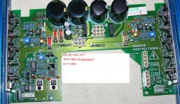
U1,U6 OP275 circuit differences?
Hi csantos,
This pcb seems difficult with no burnt or exploded parts.😕
Now this is important,I noticed your repair of the output mosfets are not in good contact with the heatsink,ie. there are gaps or spaces between mosfet
and heatsink.This is a sure disaster and the new mosfets will fail quickly.
Better yet to use heatsink grease/compound for better heat conduction.
From your description only the mosfets on channel A is the bad side.
And because of the improper mounting is causing the problem? Tip: clamp
the mosfets first and then solder ,that will ensure good contact with heatsink
and also better to use heatsink compound with them.
As the post header says there are differences of both channel A and B of
the circuit components of U1 and U6 OP275: See uploaded image TOP_A
I have put red arrows to show the differences on both circuits.
ChannelA Channel B Good channel
R19 is empty = R64 = empty
R25,26 (9.1Kohm?) = R71 (9.1Kohm) , R72 (empty)?
C3 = 10nF 100V = C33A = empty?
I would think that both channels A,B in this part of the circuit (driver?)
should be the same? Please check all other components for short or open
circuit. Singa
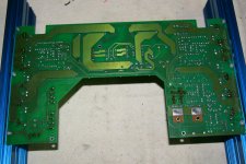
oops second picture is a mistake, I meant to post the bottom side of pcb so others
can trace the connections.
Hi csantos,
This pcb seems difficult with no burnt or exploded parts.😕
Now this is important,I noticed your repair of the output mosfets are not in good contact with the heatsink,ie. there are gaps or spaces between mosfet
and heatsink.This is a sure disaster and the new mosfets will fail quickly.
Better yet to use heatsink grease/compound for better heat conduction.
From your description only the mosfets on channel A is the bad side.
And because of the improper mounting is causing the problem? Tip: clamp
the mosfets first and then solder ,that will ensure good contact with heatsink
and also better to use heatsink compound with them.
As the post header says there are differences of both channel A and B of
the circuit components of U1 and U6 OP275: See uploaded image TOP_A
I have put red arrows to show the differences on both circuits.
ChannelA Channel B Good channel
R19 is empty = R64 = empty
R25,26 (9.1Kohm?) = R71 (9.1Kohm) , R72 (empty)?
C3 = 10nF 100V = C33A = empty?
I would think that both channels A,B in this part of the circuit (driver?)
should be the same? Please check all other components for short or open
circuit. Singa
oops second picture is a mistake, I meant to post the bottom side of pcb so others
can trace the connections.
Attachments

Last edited:
Hi singa,
I have been careful in assure that the mosfets are in good contact with the heatsink.
Only when i take the fotos i was like that.
By the way, between the mosfets and the heatsink there´s a kind of mica but is a conductive material. theres no problem right? As the mosfets drain is comon between each three.
But measuring the conectivity between the drain and the heatsink on the B channel i noticed there´s not a value of zero ohm like in channel A.
I dont know why, if it have the same kind of conductive mica, how can´t be conection between the mosfet and the heatsink?
But anyway, i think it doesn´t matter right?
Sorry about my english, hope you understand me.
The differences you well noticed are there in fact. I haven´t removed anything from that part of the circuit. The other (good) monitor has exactly the same diferences.
And i have measured the tension values on that resistors too and have the same values of the other monitor.
It´s weird this problem... Could the mosfets be oscilating or somewhat?
Do you think that´s not a bias setting problem?
The bias pot conects to a temperature sensor LM335 that´s on the heatsink too, could it have something to do with the problem?
Again, the tension values on it, have the same values of the good monitor.
I don´t know what more i could do in this circuit.
Thanks for you help.
santos, Let's not bother about OP275 circuit since the other good monitor is the same but look at the output section.You say the drain is making contact with the heatsink? As I said before you can get error reading because there are low ohm resistors around like 0.1 ohm resistors.If the drains of the outputs are common then there is no need for conductive isolator/mica,is it not? Isolator damaged? Please check carefully.The only way for outputs is to take them out of the circuit to confirm whether short or not.Hope you have not adjusted the bias pot or the one for "temp cal" (temperature calibration).As it make it difficult to get back to original state but you still have a good working monitor to compare.
At this point I don't know what I can help you with but maybe you compare the good monitor voltages vs the bad one.Especially the outputs and the opamp OP275? Is LM335
short? Singa.
At this point I don't know what I can help you with but maybe you compare the good monitor voltages vs the bad one.Especially the outputs and the opamp OP275? Is LM335
short? Singa.
Last edited:
Hi again,
I made some progress, i put new mosfets and without the fuse that blows in the circuit i can have the rest of the amp working.
Then i reconect the fuse and start increasing the tension with my voltage regulator carefuly, touching the mosfets to see if it warms a lot.
At some point i realized that the amp is working (touching with my finger in the input) so the amp section is working but one or two mosfets are very very hot!
Of course i can only do this with the overal tension at maybe 70% of what it should be. If i put the tension at 100% the fuse and mosfets blows again.
So, could this hapen because of a wrong bias setting?
Give me your opinions please.
Thanks
Good, that is a big clue. Check these 2 big electrolyt, from getting dry. I see no small supply capacitor to help them. If they get dried, the system will oscillate. Your progress is shows it started oscillating at 70% Vsupply.
Try with placing 470nF-1uF MKM (or equal) parallel with those electrolyt. Check also its opamp supply capacitor.
And if really it is capacitor problem, replace with good one, not like this:😱
http://i48.tinypic.com/2hnw3zm.jpg
http://img197.imageshack.us/img197/6756/dalemanelnaonkyo.jpg
If not the capacitor, then try to compensate the opamp with 1nF capacitor across out and in- of the opamp leads.
You also may use only 60% supply if 70% is too hot.
Last edited:
The amp is working finally!
I removed the mosfets and mount them again carefuly, and when i turn the power up it doesn´t blown the fuse.
I think it may have been a mounting problem with the clamp that goes between the two heatsinks. It may be doing contact between the two. My fault.
Thank you very much for your help.
I removed the mosfets and mount them again carefuly, and when i turn the power up it doesn´t blown the fuse.
I think it may have been a mounting problem with the clamp that goes between the two heatsinks. It may be doing contact between the two. My fault.
Thank you very much for your help.
The amp is working finally!
I removed the mosfets and mount them again carefuly, and when i turn the power up it doesn´t blown the fuse.
I think it may have been a mounting problem with the clamp that goes between the two heatsinks. It may be doing contact between the two. My fault.
Thank you very much for your help.
Hi csantos,
Congratulations,you have learned a valuable lesson.Always make
sure your mosfets/bipolars are well insulated and double check everything
before you switch on again.😉 Ps check with continuity meter to confirm
there are no shorts between both N and P devices,plus no shorts with output and heatsink.
Singa.
Last edited:
Powersupply
hi guys, thanx for the high-res pix. i could source some differencies between the boards i bought secondhand and yours that let me start my project savely. i would like to transform a passive 2108 into an active one. i´m missing the power transformers. which one is quested using. i guess something to get +/- 15v. is there a third voltage from the main transformer? how many watts should the transformer be rated at? thanx rop
hi guys, thanx for the high-res pix. i could source some differencies between the boards i bought secondhand and yours that let me start my project savely. i would like to transform a passive 2108 into an active one. i´m missing the power transformers. which one is quested using. i guess something to get +/- 15v. is there a third voltage from the main transformer? how many watts should the transformer be rated at? thanx rop
Hi again,
today my quested monitor get me some issue again.
This time it´s in the preamp stage. It started making some random noises and then stop making any sound from the speaker.
I tested with the preamp board from the other monitor and it works.
Lately i discover that making pressure on the litle transistor on the Photo it starts working but it´s not about bad joints. Could the transistor be broken inside?
And can anyone tell me what transistor is this? J112? Thanks.
An externally hosted image should be here but it was not working when we last tested it.
J112
Typical function is a shunt muting switch. First resolder it and nearby joints you could be be stressing by finger pressure. You could also remove it to verify the function - if the amplifier then works without a muting function and you resoldered as an initial measure, just replace it.
Typical function is a shunt muting switch. First resolder it and nearby joints you could be be stressing by finger pressure. You could also remove it to verify the function - if the amplifier then works without a muting function and you resoldered as an initial measure, just replace it.
- Status
- Not open for further replies.
- Home
- Amplifiers
- Solid State
- Quested VS2108 active monitor shematic