So I have ordered a bit more pipe, over half a meter, to get me to 28Hz or so.
I don't have the room to get to 355cm - who does? 😱- but might be able to get away with about 255cm.
However, there's another option which I'm thinking might be the better one to take.
As it happens I have another RSS265HO-44 and more 250mm outside diameter pipe on the way, so can quickly concoct another to make a pair of these.
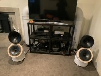
I have a question which someone might be able to answer. I can fit two of these in behind the TV so they're largely hidden, with pipe lengths of about 230cm each.
My sub amp I'm running mono/bridged currently at around 650wpc into 4 ohms (Gallo Reference3 SA) so 250 into four stereo if I build another one.
I'm just a bit fearful that two might overload the room. So should I back off on the line length and stick with say 210cm (given one already works pretty darn well) just turn the sub amp down? Or perhaps limit the line length further?
I guess this is more a matter of experimenting given each room is going to be different? Probably if I start and 210 each that might be a good compromise. Honestly, if Im only getting to 40Hz in room I don't really care because I've never had bass that sounds so 'right' before now.
I don't have the room to get to 355cm - who does? 😱- but might be able to get away with about 255cm.
However, there's another option which I'm thinking might be the better one to take.
As it happens I have another RSS265HO-44 and more 250mm outside diameter pipe on the way, so can quickly concoct another to make a pair of these.
I have a question which someone might be able to answer. I can fit two of these in behind the TV so they're largely hidden, with pipe lengths of about 230cm each.
My sub amp I'm running mono/bridged currently at around 650wpc into 4 ohms (Gallo Reference3 SA) so 250 into four stereo if I build another one.
I'm just a bit fearful that two might overload the room. So should I back off on the line length and stick with say 210cm (given one already works pretty darn well) just turn the sub amp down? Or perhaps limit the line length further?
I guess this is more a matter of experimenting given each room is going to be different? Probably if I start and 210 each that might be a good compromise. Honestly, if Im only getting to 40Hz in room I don't really care because I've never had bass that sounds so 'right' before now.
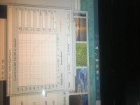
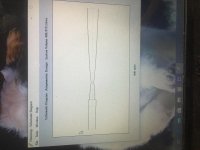
Here’s Greg’s suggestion at 355 cm. Using Your 438cm2 pipe with two drivers in that 355cm length or a single driver shown in overlay. Black is two drivers. You’d need to make a throat chamber (box for the two drivers two fire into that joined to the single 438cm2 pipe. (Typical ) . If only one driver, you can stuff it, but getting the 355cm length is more important than any compromises used to spare pipe material or facilitate two pipes and two drivers. The Pipes CSA and driver Vas don’t cooperate for the Fb that’s ideal here in a straight TL shape(constant CSA). However it looks happy as heck at 355 cm if two drivers share one pipe. (Not two girls one cup 😱 lol.
Correct me if I’m wrong, but tuning these to 40 hz is less than ideal. WAy far from ideal.. A bit of wasted effort that can otherwise easily be a rather nice sub if given the 355cm qw length for Fs of 21hz.
Correct me if I’m wrong, but tuning these to 40 hz is less than ideal. WAy far from ideal.. A bit of wasted effort that can otherwise easily be a rather nice sub if given the 355cm qw length for Fs of 21hz.
Attachments


Okay, thanks for that. Understood but 355cm is 3.5m which is over 11feet, and would be like a boa constrictor in the room. I'd never get away with that.
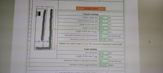
Which is why initially Im going for this; see attached. The classical fit which, according to the mhaudio.nl calculator I used will get me to 28Hz with 247cm of line.
By the by, its low tuning gets you to 21Hz with 330cm of line length, no terribly dissimilar to the 355cm quoted.
Given I'm only at a theoretical 40Hz or so now, I'd have thought the extra length to 247cm and 28Hz is worth aiming for first.
Attachments
And by the by, even as is, at what is probably about a 40Hz tune, the in-room bass is mesmerising. Clearly I hadn't optimised my 15-inch sealed sub because this incomplete 10-inch TL sub is in another league of better. I always thought sound quality was best with sealed but this seems more real, closer to the real thing, truth of timbre and all that. Plus there's more whomp there, much more. And potentially there's more to come
This evening I intend trying to mate extra length to the line, even though I dont have ideal Lego interlocking line bits. Will just have to suffice with taping them together. 😉
This evening I intend trying to mate extra length to the line, even though I dont have ideal Lego interlocking line bits. Will just have to suffice with taping them together. 😉
Last edited:
And by the by, even as is, at what is probably about a 40Hz tune, the in-room bass is mesmerising. Clearly I hadn't optimised my 15-inch sealed sub because this incomplete 10-inch TL sub is in another league of better. I always thought sound quality was best with sealed but this seems more real, closer to the real thing, truth of timbre and all that. Plus there's more whomp there, much more. And potentially there's more to come
This evening I intend trying to mate extra length to the line, even though I dont have ideal Lego interlocking line bits. Will just have to suffice with taping them together. 😉
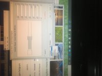
This might help? I have it drawn wrong and simmed without the first harmonic null up at ~90hz or so... this would have the drivers and the exit of the pipe at the same end. I drew an offset driver mistakenly...
Attachments
Last edited:
Can you please explain where the S1, S2, S3 and S4 parameters come from?
In other words the 438 figure?
Brian Steel did a similar thing with this driver but his S1-4 figures were 370 odd and he got a line of 310cm.
Sorry but Im not familiar with hornresp.
Appreciate the help.
Cheers
Peter
In other words the 438 figure?
Brian Steel did a similar thing with this driver but his S1-4 figures were 370 odd and he got a line of 310cm.
Sorry but Im not familiar with hornresp.
Appreciate the help.
Cheers
Peter
Last night I extended the line to 2.4m and felt I heard a further extension of deep bass. Which makes me wonder how it would sound when the python was fully in the room.
So I have come up with a cunning plan, a plan so cunning you could pin a tail on it and call it a weasel, to quote a certain Blackadder.
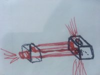
What I plan to do is create an inverted U shape of PVC tubes so that the end of the line looks like the beginning, only on the far side of the equipment stand and TV, and without a woofer at the far end. At which point the line will be 3.3m or thereabouts. So we should get down well into the 20s in room, as the calculators suggest.
But then I had another plan, which probably isn't so cunning at all, but worthy of running past people who have been in the quarter wave and transmission line game for a much longer time than I have. It's probably silly but worth asking I think.
I have another identical RSS265HO-44 woofer on hand and am wondering whether I can insert this into the other end of the 3.3m line and hook it up opposite phase, so in pus- pull configuration.
I realise that the line would then be closed and therefore this may not work, but thought I would run it past the experts for their opinions.
Any comments would be greatly appreciated.
Regardless of whether this is a runner or not, I can quickly and simply check out what one correct length line sounds like with one woofer compared with two lines and two woofers that I think I can get to 2.4m each without too much trouble. It will be an interesting comparison.
So I have come up with a cunning plan, a plan so cunning you could pin a tail on it and call it a weasel, to quote a certain Blackadder.
What I plan to do is create an inverted U shape of PVC tubes so that the end of the line looks like the beginning, only on the far side of the equipment stand and TV, and without a woofer at the far end. At which point the line will be 3.3m or thereabouts. So we should get down well into the 20s in room, as the calculators suggest.
But then I had another plan, which probably isn't so cunning at all, but worthy of running past people who have been in the quarter wave and transmission line game for a much longer time than I have. It's probably silly but worth asking I think.
I have another identical RSS265HO-44 woofer on hand and am wondering whether I can insert this into the other end of the 3.3m line and hook it up opposite phase, so in pus- pull configuration.
I realise that the line would then be closed and therefore this may not work, but thought I would run it past the experts for their opinions.
Any comments would be greatly appreciated.
Regardless of whether this is a runner or not, I can quickly and simply check out what one correct length line sounds like with one woofer compared with two lines and two woofers that I think I can get to 2.4m each without too much trouble. It will be an interesting comparison.
The issue with just placing any driver in any size pipe at a qw (plus end correction) length is that you must also keep the driver happy. IN order to do so the size of the pipe is almost NEVER the size of the driver. In fact this rss265ho44(?)prefers a changing CSA as Greg originally shared in the Hornresponse txt he posted that went from 576 to 176cm2. Or if only able to use a certain pipe, in this case 438cm2, you need to cut it in half the length wise direction or use two drivers. Obviously cutting it doesn’t work so placing a solid inside the pipe does. A number of long framing studs for building construction are dirt cheap and easily cut to size and altered in the amount and area they consume.
What you are ‘fighting’ is essentially what’s seen in the Vas component iwhere compliance is shown as a measure in air volume that will ‘neutralize’ or is equal to the suspension and soft parts rigidity or stiffness. You need to present a feeling to the driver at the cone surface that it’s in a certain volume of air to play well but not have issues in certain areas and in the case of a qw tuning length and frequency this volume of air the rss seems happy in looks to be about what the pipe presents the cone with if given a 576-176 section at the length stated by GM. Or you can shove two drivers into the 438cm2 pipe confines for a length closer to 350 then not. You could also just guess and shove 5 pillows in the 438cm2 pipe with one driver at a guessed length per 1130/frequency with an end correction and shoot for Fs or slightly below it. But guesses and transmissionlines don’t work so much. That’s a guess to, lol, but I did get lucky once upon a time prior to horn response, so I’m
Not sayingblucky isn’t a thing. But They didn’t for over half a century prior to good simulation software, nothings changed about guessing. But math or sim seems to be solid these days? If the Vas and Q values for the rss are as published 35liters and 0.45 with an Fs of 27.5hz then it wants a 350 cm pipe at a relatively smaller than Sd diameter. 438cm2 is not that size. Unless you’re using a limited input power and never RMS or even close its literally stuffed like crazy or 150 cm2 and even both.
At 438 and like 200 watts you’re at Xmax with spiked ends of response SPL bandwidth. There’s a lot of ways to resolve that, in the bandwidth area, not below it... easiest is the correct pipe or pipes diameters. Hardest is slamming the moving motor bits against non moving bits at 30mm(?). The sim Is overly conservative and it’s estimated excursion and peaks/valleys a bit over zealous in the safe direction.. But that doesn’t mean they aren’t telling us something that needs to be addressed. It’s your driver(s), so it’s also your guess.
Have fun, but don’t crank up the knob if you have a house party��������
Last edited:
If you put two drivers in the opposite ends of a pipe I thinkwhst you have done is created a dual driver sealed box? Other than some internal cancelation at some 1/2 wave length in the middle of the sealed up box response when they ‘meet’ but isn’t audible there, or is outside if you stand in the middle of the two seperate drivers I don’t have much of a clue. Maybe it’s more than that, but I don’t know or think I might.
BW
Thanks for the comments. They are much appreciated.
I wasn't prepared to build a box, but I could have simply begun with a bigger tube, and routed a circle for the driver. I could then have used joiners to taper the line. However, the bigger tube was ruled out by SWMBO. Only just got away with the 250 outside diameter tube.
So I'm going to have to work with what I have. Noted that there is more than one way to skin a cat. I intend to try tapering the line as you suggested, using internal modifications, simple things like pillows but Im also wondering whether thick foam insulation (like the cheap stuff for houses) that I can cut to various shapes and glue into the tubes might also be a cost effective way of making a rough taper?
The other thing I intend to do is try installing the other 10-inch driver in the end of the line and check out how two 240cm lines work together, ie, as dual subs. Given the 240cm line with one sub worked pretty well, it might be interesting to see how two of them fire. Plus it's only a half-hour job to make the change.
Regarding drive, I don't do party level SPLs. So it is most unlikely that I will push the driver to its limits unless the current design is miles away from optimal. I have been checking out its excursion during low notes and it doesn't seem to be under any stress. Nor are there any noises that suggest as much. That said, it moves more than when it was in sealed or ported designs. So it is obviously working harder. But then it's digging lower too, so you'd expect that.
Again, thx for the advice.
P
If you put two drivers in the opposite ends of a pipe I thinkwhst you have done is created a dual driver sealed box? Other than some internal cancelation at some 1/2 wave length in the middle of the sealed up box response when they ‘meet’ but isn’t audible there, or is outside if you stand in the middle of the two seperate drivers I don’t have much of a clue. Maybe it’s more than that, but I don’t know or think I might.
Correct!
My 'adventures' in pipe/horn design got the attention of a co-worker's dad that had a similar passion except for using only sealed pipes, though loaded with more upscale drivers, with the best of the bunch being functionally a plane wave tube [PWT] and 'our' fave, his near ceiling height corner loaded pipe with end loaded 8" 'FR' drivers [a $1.00 used back then, now 'heirloom' priced Altec 755] to create what at the time seemed the most realistic sounding 'stereo' system from a mono speaker. Sure was a pain though to find the optimum sounding end gaps, which surprisingly to us technically 'challenged' types were not the same at each end.
Should be a 'walk in the park' for DIYers nowadays though, or guess just DSP its response with matching gaps.
Re driver effective motor strength Vs pipe area, B0$3 addressed this in their Wave Cannon patent: https://patentimages.storage.googleapis.com/20/33/d4/83f24455bfcc7f/US4628528.pdf
Pg. 9, 6/58:
"For a given ratio of [Bl]^2/Re the ratio of tube to cone areas (ATCR) typically controls the size of the system response peaks at the frequencies where the tube length is an odd multiple of a quarter wavelength for a single tube. For some typical speakers and an ATCR of 1 these peaks are relatively large. For ATCR of 0.5, the system response is relatively smooth. For ATCR less than one half, system response decreases because the tube provides increased load on the loudspeaker cone."
IOW, for typical woofer specs a 2:1 CR is desirable for adequate acoustical damping, i.e. little/no actual stuffing required, so a sub at each end gets close enough for a DIY app just as HR predicts, though of course less is always less, so an earlier roll off slope, at least until thermal power compression in high power apps reshapes the response.
GM
Holy sh!t! I gotta take notes, this is some good good info training���� Right hete^^^
I need to look at my junk and see how the CR plays out in the current boxes I have. And the 450 liter with a single 12” huge expanding path ‘pipe dream’ that really pushed the envelope needs expert an critique before I take it seriously enough to put the wood on the saw. I’ve got a sideways spin off the main ideas surrounding MMJs offspring. That he and I with a couple other dudes messed around with all night in a private chat group for speaker gerks��and played with ideas that are probably going to bear fruit shortly by one of the guys, if not myself, or both...build it or my slightly altered version.
I need to look at my junk and see how the CR plays out in the current boxes I have. And the 450 liter with a single 12” huge expanding path ‘pipe dream’ that really pushed the envelope needs expert an critique before I take it seriously enough to put the wood on the saw. I’ve got a sideways spin off the main ideas surrounding MMJs offspring. That he and I with a couple other dudes messed around with all night in a private chat group for speaker gerks��and played with ideas that are probably going to bear fruit shortly by one of the guys, if not myself, or both...build it or my slightly altered version.
Last edited:
That's what is such a blast about this forum. I understand about a tenth of the replies but right now I suddenly have subwoofing that is in another league of outstanding compared with my previous decades of ******* around with sealed and ported subs.
I realise it is nothing like optimal but sometimes aesthetic compromises are required, heh heh.
Tonight I rolled some 200mm diameter tubes in flexible vent insulation, and inserted them in the middle and end of the line. Took no time at all really, and surprisingly, they are nicely stuck in there so I guess those are the beginnings of a taper.
The bass quality and quantity are simply outstanding to my ears - no measurement gear soz so it doesn't count - and the driver seems totally unstressed about it all. Even on the deepest notes its excursion doesn't seem excessive. And there are absolutely no audible signs of stress.
The other aspect of this bass I like is that it is kind of a really nice halfway house between weak and wimpy but accurate open baffle bass and ported bass that sometimes seems not so musical.
Will try stereo lines over the weekend given how simple they are to rig up.
Even though it is no thing of beauty, functionally the silver arch utterly destroys anything I've had in the system before. So thanks for the advice those who have taken the time.
I need to look at my junk and see how the CR plays out in the current boxes I have.
And the 450 liter with a single 12” huge expanding path ‘pipe dream’ that really pushed the envelope needs expert an critique before I take it seriously enough to put the wood on the saw.
What kind of box alignments? Basic vented box ratio for optimal transient response is Vb = Vas/1.44 tuned to Fs.
Do tell; seriously, do tell. 😉
GM
What kind of box alignments? Basic vented box ratio for optimal transient response is Vb = Vas/1.44 tuned to Fs.
Do tell; seriously, do tell. 😉
GM
I avoid bass reflex and mltl more often than not these days. But this is neither. I have a couple Paraflex cabinets and one is actively in use and current. The things are very exciting and the hype is real... I tried tweaking it a bit and expirimented with offset driver positions and all kinds of exit CSA changes to alter things to get the most bang for the buck in a given size... good stuff lots of fun, but I started this all speaker building stuff with mid 20hz Fs drivers about a year ago in the Mass loaded taped qw pipe styles and Fb in the low to mid 20s, not 36....paraflex is 36 no if, ands or butts in a 160 liter cabinet for any 12 that’ll perform in it.(there’s not a whole lot that want too).
Long story short I started making isobaric pairs with the old low Fs drivers tuned to those depths in the 20d and now have that AND a Paraflex to subwoofer and super subwoofer the lowest octaves with.
But the fun never ends in DIY and the ability to wisely use real estate in a horn loading like a paraflex provides to both sides of the cone has some delicious results. I’m touching 30hz periodically(at Xmax) with the single 12” driver I’m currently using in the real paraflex. So here’s some pics
Attachments
I hope it’s okay Peter? ^^^^ I don’t wanna cut in your post here. But the rss265 and 315 ho4 Models work in similar paraflex designs you might be interested in down the road in future adventures?
No I dont mind in the slightest!
I've not heard of paraflex before.
I would be interested to hear about your isobarics too, any images of those and the paraflex you could post?
I've not heard of paraflex before.
I would be interested to hear about your isobarics too, any images of those and the paraflex you could post?
And one other thing; I now have a
Dayton RSS390HO-4 15" Reference HO Subwoofer 4 Ohm sitting around that i should be doing something with😉
Dayton RSS390HO-4 15" Reference HO Subwoofer 4 Ohm sitting around that i should be doing something with😉
And I just discovered a whole lot of designs that are detailed here:
New sub design? Constricted Transflex, simple build (series tuned 6th order)
New sub design? Constricted Transflex, simple build (series tuned 6th order)
- Home
- Loudspeakers
- Subwoofers
- Quarter wave enclosure for Dayton RSS265HO-44?