600ohms.Sounds very useful.
What input and output resistances ?.
Can you give a schematic please ?.
Dan.
each T attenuator is built to 600ohms.
I posted an excel spreadsheet with a few different types of attenuator in there.
The T attenuator is included along with the calculator to build up individual switches. The sch is there so that one can "see" where the three resistors go around the switch terminals.
Just string as many switches together for as many steps your require.
I used 20, 10, 5 ratios.
-20, -20, -10, -5, -2, -2, -1, -0.5, -0.2, -0,2 -0.1, -0.05.
All switches OFF = -0dB, all switches ON = -61.05dB
The difficult part is obtaining sufficient absolute accuracy for the resistor values. This becomes a severe problem for the -20db and -10dB attenuators where simple 0.1% tolerance is not good enough to be better than the least step of 0.05dB.
If I have a low accuracy DMM, I can get very good comparison measurements using the following method.
Insert the attenuator before the input to the amplifier.
Set the switches to approximately match the gain of the amplifier.
Apply a sinewave test signal of ~ 1.9Vac. This will read as 1.9xxVac on a DMM set to 1.999Vac.
Measure the output signal. It will be close to the input at the attenuator. adjust the attenuator until the output reads near enough exactly the same as the input.
You now have a "comparison" measurement at the SAME frequency and at the SAME voltage, using a signal that has virtually the SAME distortions, so a very poor accuracy DMM with an UNKNOWN frequency response will read the SAME measurement.
The accuracy of the comparison is limited by the accuracy you built into the individual steps of the switchable attenuator.
By The Way (BTW), a step of 0.05dB is a ratio of 1.00577 i.e. a change of 0.6%, the worst case closest you can get to an exact match of input to output voltages is roughly 0.3% i.e. you are approaching the limit of a 2000count DMM.
A 4.5 digit DMM gets you closer. I am lucky I have a 50000count Bench DMM and using this to cross check my three 2000 count DMMs shows that meter accuracy is NOT a problem, since we are using "comparison" and not absolute.
Another BTW, I have used this upto 50kHz and the meter frequency response is way down, I seem to recall readings of 500 to 600mVac even though the scope shows that the test signal is still up at around the 1.9Vac
Last edited:
Earlier I mentioned that the input z is 10K. you could use that and a selectable/variable series r for your attenuator (?).
Also, I suggested using a cheap auto-ranging DVM IC to do the auto-ranging for you with outout going to relay drivers. replay contacts would go to select IP voltage divider.
Just some ideas for you.
I have several analyzers.... but still appreciate the QA400 for its ease of use and PnP operation. And, it is very portable. Whereas, my other analyzers are not (bench equipment).
THx-RNMarsh
Did you know, that it is going to make a QA405, at the end of 2015?
Input attenuator 1X/0.1X/0.01X, selectable input and output resistance, larger buffer, ac/dc coupling inputs and so many.
More info: https://www.quantasylum.com/content/Home/tabid/40/EntryId/33/QA405.aspx
Input attenuator 1X/0.1X/0.01X, selectable input and output resistance, larger buffer, ac/dc coupling inputs and so many.
More info: https://www.quantasylum.com/content/Home/tabid/40/EntryId/33/QA405.aspx
@ AndrewT,
Thanks for your post. I have an HP 350 D stepped attenuator
that goes from 0 thru -110 dB:
0,...1,...2,...10. dB
0, ...10, ... 20, ... 100 dB
However from what I can gather this is a
DC RF attenuator that should be used with
50 VDC or 55 VDC. The manual says to
call the factory for calibration for use
with AC signals.
Now I'm wondering after reading your post
and I haven't gone through the measurement steps yet
to either modify it with a switch and pot to dial in the
appropriate attenuation for lower voltage AC use.
Or make a simple feed through BNC to Banana switched
attenuator for correction.
Manual:
Sorry, can't get it to link/upload etc.
Last edited:
Trying to do the voltage check on the attenuator.
However, it doesn't scale the way I thought.
Here is a table provided by HP to check the
voltage and the attenuation. (When I place
it in the gallery first. )
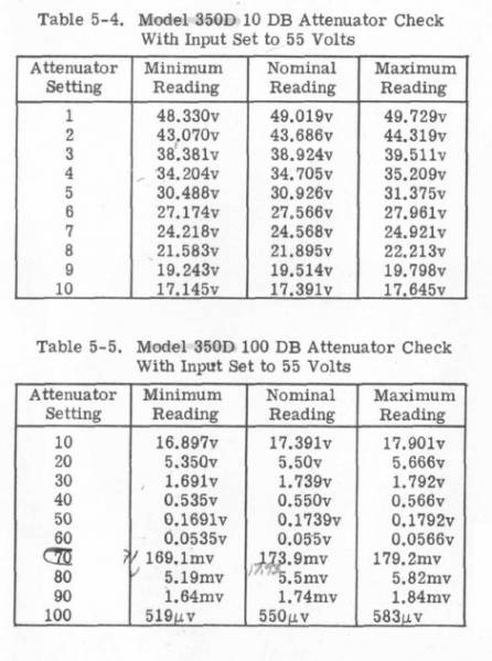
Note: As I try to scale the voltage, that is using 5.5V versus 55V
I get completely different reading then in the table.
55V @ -1dB = 49.019V
Expected:
5.5V @ -1 dB = 4.9019V
Measured:
5.5V @-1 dB = 5.4037V
NUTS, The voltages are VAC, not VDC.
Hmmm....thinking none of my supplies
goes up to 55VDC. And scaling down a
tube amp for a 55VDC is do able but can
get tricky and dangerous connecting,
disconnection, touching the wrong thing
Especially with a 23 month old kid running
around thinking she owns the place and won't
take no for an answer.
Last thing I want is to turn if she runs in and
touch or ground hot through me or her.
However, it doesn't scale the way I thought.
Here is a table provided by HP to check the
voltage and the attenuation. (When I place
it in the gallery first. )
Note: As I try to scale the voltage, that is using 5.5V versus 55V
I get completely different reading then in the table.
55V @ -1dB = 49.019V
Expected:
5.5V @ -1 dB = 4.9019V
Measured:
5.5V @-1 dB = 5.4037V
NUTS, The voltages are VAC, not VDC.
Hmmm....thinking none of my supplies
goes up to 55VDC. And scaling down a
tube amp for a 55VDC is do able but can
get tricky and dangerous connecting,
disconnection, touching the wrong thing
Especially with a 23 month old kid running
around thinking she owns the place and won't
take no for an answer.
Last thing I want is to turn if she runs in and
touch or ground hot through me or her.
Last edited:
Shame on me...as I was typing that into here
she came running over to me and put her on
my lap. Only to get my jeans and leg filled
with pee from her now full and overflowing diaper.
Her love for me truly runnith over.
This was the exact same concern I was having
but glad I am only typing and not measuring
some 600V tube amp.
she came running over to me and put her on
my lap. Only to get my jeans and leg filled
with pee from her now full and overflowing diaper.
Her love for me truly runnith over.
This was the exact same concern I was having
but glad I am only typing and not measuring
some 600V tube amp.
Trying to do the voltage check on the attenuator.
However, it doesn't scale the way I thought.
Here is a table provided by HP to check the
voltage and the attenuation. (When I place
it in the gallery first. )
Note: As I try to scale the voltage, that is using 5.5V versus 55V
I get completely different reading then in the table.
55V @ -1dB = 49.019V
Expected:
5.5V @ -1 dB = 4.9019V
Measured:
5.5V @-1 dB = 5.4037V
NUTS, The voltages are VAC, not VDC.
Hmmm....thinking none of my supplies
goes up to 55VDC. And scaling down a
tube amp for a 55VDC is do able but can
get tricky and dangerous connecting,
disconnection, touching the wrong thing
Especially with a 23 month old kid running
around thinking she owns the place and won't
take no for an answer.
Last thing I want is to turn if she runs in and
touch or ground hot through me or her.
If the table is scaled for DC then you have to use Vrms for ac.
Remember that Vrms is the equivalent heating value of DC.
What do you mean by DC RF?
RF is commonly measured in power gain, dBmW.
In such a case it's 10*log(P)
Are you sure it's not calibrated for power gain?
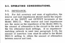
(Edit) Okay. I'm looking at the manual now. This is not a RF attenuator although it has a range of DC to 1MHz. Your 350D is 600 ohms in and out.
What is the input impedance of you source. I think the attenuator is expecting 600 ohms.
I'll read the manual.
According to the manual it's calibrated for dBV.
RF is commonly measured in power gain, dBmW.
In such a case it's 10*log(P)
Are you sure it's not calibrated for power gain?
(Edit) Okay. I'm looking at the manual now. This is not a RF attenuator although it has a range of DC to 1MHz. Your 350D is 600 ohms in and out.
What is the input impedance of you source. I think the attenuator is expecting 600 ohms.
I'll read the manual.
According to the manual it's calibrated for dBV.
Attachments
Last edited:
Hi David,
Yep. Either before or after where the tables
are presented in the manual was the section
for AC use. Call the factory.
My bad, I'm trying to figure all this out.
And have just posted my observations
however flawed they are.
The output impedance of my source (for now)
the Leader Function Generator LFG 1300s is
50 ohms.
I'm going into the 350D then out from the 350D into my
HP339A. I'm in the process of comparing voltage measurements
from source, though attenuator...then, comparing HP339A volt meter
to the bench meter I have, HP 3468A.
I've just gotten the Leader working at the moment and thought
I'd start measuring distortion with my QA400. I stopped by this
thread.
I had the little HP350D box sitting around and after reading AndrewT
post remembered why I got the 350D, so I could have some type
of variable front end to the QA400 and have a method to attenuate
them.
To add another layer of stuff into all of this, early on you Richard,
RichEEM, Demian, were discussing impedance matching problems
over on the long distortion thread and maybe in this thread too.
At a junk shop, I picked up this thing thinking I could use the knobs
for my HP339a. But as it turns out, I think I can actually use the little
box also for matching impedance. You've got to remember I'm on
an extremely limited budget so I have to take my time and strategize
each purchase and have reasonable assumptions that if the thing doesn't
work can I fix it and make it work? Can I part it out and sell it?
Anyway always appreciate your help.
Okay.
You can match the impedance by inserting a 550 ohm resistor in series with the Leader.
You will have to account for the insertion lose. This will satisfy the 350D but perhaps not the leader. But it doesn't matter if it's a 50 ohm series R at the Leader's output. You can use a 600
ohm resistor in parallel with the output of the 350D. The 10k input Z of the QA400 won't weigh on the 600 ohm much. If the Leader is a 50 series R + 550 ohm the attenuation into the 350D will 0.5, 50% and same attenuation at the output of the 350D.
This should give a reasonable impedance match.
I don't understand HP's comment about consulting the factory about AC use. What else would the thing be for if it's calibrated in dBV. Certainly not DC. For DC a decade box would do.
There is no such thing as DCdBV.
Trying to do the voltage check on the attenuator.
However, it doesn't scale the way I thought.
Here is a table provided by HP to check the
voltage and the attenuation. (When I place
it in the gallery first. )
Note: As I try to scale the voltage, that is using 5.5V versus 55V
I get completely different reading then in the table.
55V @ -1dB = 49.019V
Expected:
5.5V @ -1 dB = 4.9019V
Measured:
5.5V @-1 dB = 5.4037V
NUTS, The voltages are VAC, not VDC.
Hmmm....thinking none of my supplies
goes up to 55VDC. And scaling down a
tube amp for a 55VDC is do able but can
get tricky and dangerous connecting,
disconnection, touching the wrong thing
Especially with a 23 month old kid running
around thinking she owns the place and won't
take no for an answer.
Last thing I want is to turn if she runs in and
touch or ground hot through me or her.
I don't know what your test and measurement setup is, nor exactly what the objective of these measurements is, but let me offer some comments that may help clarify your thinking. Many incarnations ago I used HP 350D attenuators on a weekly (or more often) basis. Although it has been a few decades since I had occasion to touch one, there should be enough residual memory to assist you.
- The HP 350D is a resistive attenuator - I'm confident its circuit design is PURELY resistive. By its nature, the indicated attenuation value will be accurate ONLY if BOTH the Thevenin impedance of the source driving the attenuator, AND the impedance of the load driven from the attenuator, match the attenuator's design impedance (e.g., 600 ohms for the HP 350D). Somewhere in the HP 350D Service Manual there is probably a graph or table showing the additional attenuation error when the source and/or load impedance is NOT exactly 600 ohms.
(The amount of this additional error is also affected by the attenuation setting of the HP 350D. If I recall correctly, it's also more sensitive than most of us expect - just 10 or 20 ohms error in the source or load impedance can double the 350D's inaccuracy.) - The HP 350D should have a flat frequency response (within a fraction of a dB) from DC up to 1 MHz or so. It's useful into the HF frequency range (10 MHz or more) if you can tolerate the frequency response rolloff, and reduced accuracy.
- By their nature, attenuators of this type can be made quite accurate with relatively low cost. If I can figure out some way to make a measurement using an attenuator as the actual measuring standard, that measurement is likely to be more accurate than the same measurement done with a common meter or test set. In other words . . . I'd use the attenuator to check the accuracy of my meter, rather than using (most) meters to check the accuracy of my attenuator.
- There are several practical implications of these previous two points. The one most immediately applicable to this particular discussion is that a D.C. voltage - which can, in fact, be measured rather accurately - can be confidently used to calibrate (or at least verify the calibration) of an attenuator used at frequencies quite a bit above D.C.
- Passive attenuators of this type are insensitive to the signal levels they are used at, within reason. If you use a signal of, say, 1 volt to adjust an attenuator to have a certain attenuation, then you can be assured it will present the same attenuation to a signal of less than 1 millivolt.
(As I said, there are practical limits. High signal levels will cause heating of the resistive attenuator elements, resulting in errors due to component temperature coefficients. At very low signal levels - microvolts - the attenuation will still be accurate, but attempts to measure signal levels will be hampered by the presence of wideband noise.) - Physical damage is just about the only thing that can go wrong in a 350D. Even a severely banged-up case is likely to house an attenuator that fully meets performance specs of a new unit.
But in this context, "physical damage" includes electrical abuse - application of excessive input voltage. I suspect, but don't know, the attenuator resistors would tend to fail catastrophically, rather than shifting value out of tolerance. (They are probably precision, non-inductive, wirewound resistors that retain their value up to the point where the resistance wire melts and becomes an open circuit.) If the Service Manual gives nominal values for the resistors, checking them with a moderate quality ohmmeter should give you adequate assurance that the attenuation is accurate.
The one maintenance item that may be worthwhile is cleaning the rotary switches. These are almost certainly high-quality (close mechanical tolerance) mechanisms with electrical contacts plated by gold or other durable, corrosion-resistant, alloy. There may be some dried-out grease on the detent mechanisms, which should be wiped off and replaced by high-quality synthetic lube. I wouldn't try to burnish, polish, or chemically clean the contacts - just douse them with healthy squirts of isopropanol while operating the switch.
Dale
The 350D is a 600 Ohm constant impedance attenuator. Its attenuation is based on a 600 Ohm source and a 600 Ohm attenuator. its good for DC to probably 100 KHz. The cal table allows using a DC voltmeter (probably a Keithley 5 knob meter) to check it since accurate AC sources and measuring instruments were very rare and expensive when it was made. The high voltage was to increase the resolution on the measuring meter. 55V and -100 dB gives around 500 uV or not very much. Not many DC meters are accurate at that low level (not to mention thermals will swamp 500 uV easily).
You do not need DC for it to operate.
I believe it was created to extend the usefulness for the HP 200CD oscillator, also capable of as much as 55V.
Link to manual: http://www.nscainc.com/uploads_2014/product_guides/A_350D.pdf
There is another variation that has input and output transformers. I sold one recently to reclaim some storage space.
Last edited:
David,
Yeah, that is what I was thinking too, when I read the manual.
Call the factory for AC use?
WTF...over!
They had their conversion chart up front, but that was
for the attenuation factor.
I'm not sure how to use the attenuation factor going
from one dB to the next. Maybe multiply it by
the voltage to get the result?
I'll give that a shot and post the result.
I should get closer than I was.
Cheers,
Reading to the end of the manual, the DC is a verification test and if you are going to verify with AC call the factory. For use ac or dc, no need to call the factory. There is much expressed on proper grounding for high frequency AC use and more if there is a dc component. But for audio it should work fine with out much fuss if the in/out impedance are matched.
I'm sure by now you have gotten a lot more response on this than perhaps you have bargained for.
Nature of the thread.
I'm sure by now you have gotten a lot more response on this than perhaps you have bargained for.
Nature of the thread.
David,
Yeah, that is what I was thinking too, when I read the manual.
Call the factory for AC use?
WTF...over!
They had their conversion chart up front, but that was
for the attenuation factor.
I'm not sure how to use the attenuation factor going
from one dB to the next. Maybe multiply it by
the voltage to get the result?
I'll give that a shot and post the result.
I should get closer than I was.
Cheers,
Yes multiply the attenuation factor by the measured volts and that will be the output in volts.
20*Log(attenuation factor) gives the attenuation in dB.
10^-1dB/20 = ~0.8913. 1dB attenuation.
David, Dale, Demian,
Yes, Yes, Yes, and Thanks
yes I did find your comments helpful Dale.
The attenuator looks new, barely used.
It has HPs warning on sticker, an old NIST
calibration sticker, and on the back an old
inventory sticker, property of cochlear associates
or something.
My inserting banana plugs is cracking the
polystyrene jack bases....yes, it is of that late
era.
I have noted too that impedance mismatch will
affect the attenuation.
Yes there are diagrams in the manual and I'll study them.
I can post them for clarification when I get to it.
Cheers,
Post Script - Wouldn't you know it, the only calculator I have
is an HP12C, so I can calculate payments, bond yield, depreciation,
and standard statistics....It won't do a lot of the calculations that
I need for this stuff.
The Oracle of Sync tells me there is an old HP11C in my future.
Last edited:
David, Dale, Demian,
Yes, Yes, Yes, and Thanks
yes I did find your comments helpful Dale. . . .
I should add that I was surprised when you started talking about checking calibration with a 55 volt (yes, FIFTY-FIVE volts) test signal. I was certain that was a typo error - surely you meant 5.5 (Five-point-five) volts, or perhaps 15.5 (Fifteen-point-five) volts.
But your posted value was quite correct! The HP 350D is truly rated for a signal dissipation of five watts! If you had pressed me on the matter, I would have guessed the rating as one watt - two at the outside - and perhaps only 500 milliwatts. The five-watt (actually, 55 VOLTS rms) rating makes the thing almost bullet-proof in the DIY and hobbyist environment. Go ahead, connect the HP 350D directly to the output terminals of any power amplifier rated up to 300 watts or so into 8 ohms. The indicated attenuation value will not be accurate (because the source impedance value is not correct), but once you get above 15 or 20 dB the incremental change in attenuation from step to step should be accurate enough for our purposes.
Looks like you have a great find there!
Dale
- Home
- Design & Build
- Equipment & Tools
- QuantAsylum QA400 and QA401