The ESL-63 stator I mentioned above finished with resonant frequency at 50 Hz, which I recall from Baxandall, is about right. It seemed easy at the time, but you do have to be very, very careful avoiding sharp objects, especially 'dust' like bits of wood fibre or fine plastic shavings. Cleanliness is everything. Keep fingernails short. I wouldn't try stretching the film on wood - too risky I expect - only glass.
regards
Rod
regards
Rod
Since I measure during stretch only on stator is attached as reference I used 2 old original stators. The res is 62 with bone stator half attached an no hv connected , I will measure them tonight. With both halves attached
i wonderered about the thickness of film, since this is a stock quad nothing looks repaired not the panels nore the rest. it has the darkkish coating just like all the panels on the net have. all stator crates are the black ones.
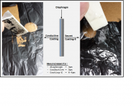
The ESL63 diaphragm I measured had a diaphragm thickness of 3µm.
The dark coating was also about 3µm thick.
Surprisingly, I found an additional coating on the back side that was clear and felt slightly rubbery and stretchy.
It appeared to be brushed on and varied in thickness across the diaphragm.
I believe this coating must be the secret damping coating mentioned in the 1989 interview with Ross Walker.
One Thing Audio/Manufacturers/Quad/History/Peter Walker
excerpt...
"We stretch it up to the required tension and stick it in the oven. In its cold form, if you stretch it, it will creep. But by putting it in the oven under tension all the molecules will line up to the most stable position so the tension won't change. This is quite important because otherwise the resonance of the speaker would change and it is carefully designed to a particular value. If it was too slack it would hit the plates, too tight the resonance would be too high. Secret ingredient X is used as a damping layer on the Mylar and then we bond the frame to the electrode structure."
Anybody familiar with Quads have any additional information on this damping layer applied to the diaphragm?
Attachments
Only very young people will be able to tell the difference between 3 um and 6 um. Cut off frequency (first order low pass) is approx. 100 kHz divided by mylar thickness. cf 28 kHz for 3.5 um and 16 kHz for 6 um.
Experimental verification of this approximation for 3.8µm, 6µm, and 12µm posted here:
http://www.diyaudio.com/forums/plan...tatic-speakers-microphones-5.html#post3427260
The ESL63 diaphragm I measured had a diaphragm thickness of 3µm.
The dark coating was also about 3µm thick.
Surprisingly, I found an additional coating on the back side that was clear and felt slightly rubbery and stretchy.
It appeared to be brushed on and varied in thickness across the diaphragm.
I believe this coating must be the secret damping coating mentioned in the 1989 interview with Ross Walker.
One Thing Audio/Manufacturers/Quad/History/Peter Walker
excerpt...
"We stretch it up to the required tension and stick it in the oven. In its cold form, if you stretch it, it will creep. But by putting it in the oven under tension all the molecules will line up to the most stable position so the tension won't change. This is quite important because otherwise the resonance of the speaker would change and it is carefully designed to a particular value. If it was too slack it would hit the plates, too tight the resonance would be too high. Secret ingredient X is used as a damping layer on the Mylar and then we bond the frame to the electrode structure."
Anybody familiar with Quads have any additional information on this damping layer applied to the diaphragm?
the 3 Um with around 2-3 um coating could be what i measured as well. but the secret ingredient X, i dont see anything or feel anything on the backside. of an original foil. well i cant hardly believe they did anything on the backside. but if someone knows more im interested
well i try tomorow to strech a foil, then heat it. then stretch it. because as what walker says he just put it in heat it and done.. if you do that you will end up with a verry low resonance foil. or he stretched it even harder then heated and it ended up at there deired res.. well i can try both. since i meaured panels that i did 4 days back and they dropped 2 hz since they where measured directly after glueing. but this could be the glue itself creeping or setting, maybe i removed them to early. who knows
exact figures i will get tomorow. i will remeasure the creeping panels as well , if it remained stable i removed them to early. i dont have time to wait more then 3 hours for the PU to dry 🙂 inpatience cost me so much time as usual 🙂 haha
exact figures i will get tomorow. i will remeasure the creeping panels as well , if it remained stable i removed them to early. i dont have time to wait more then 3 hours for the PU to dry 🙂 inpatience cost me so much time as usual 🙂 haha
well i try tomorow to strech a foil, then heat it. then stretch it. because as what walker says he just put it in heat it and done.. if you do that you will end up with a verry low resonance foil. or he stretched it even harder then heated and it ended up at there deired res.. well i can try both.
Quad held tension with distributed hanging weights while the diaphragm was heated.
After cooling it was attached to the frame, still being held at the same tension.
Attachments
aha yeah seen that one before , although this is for the quad 57, wich could easily be done with non tensilezed mylar, hence they heated it. its not clear if they do it with the 63 wich was produced much later maybe then they did use mylar C
by the way i just glued one film wich i heated during stretch then the resonance dropped to 30 then restretched it (just like they did) wonder if it remains stable, but to confirm they did it this way my other panelss should still be creeping
by the way i just glued one film wich i heated during stretch then the resonance dropped to 30 then restretched it (just like they did) wonder if it remains stable, but to confirm they did it this way my other panelss should still be creeping
Small update, all panels are playing at the moment , 6 of the 8 i redid with 3micron, in the end its not hard at all to stretch them, i had to put some tape over the corners when lightly stretched. then stretch to required tension. only problems where valves that tend to leak a bit of air when the presure is not high. wich resulted in 2 panels dropping resonance ~4 hertz under what i was aiming for. now under the HV condition res drops (7-10 hetz) to the required 50-55 hertz. what i read on the inet they cant play loud and dont have much low end. well i disagree. i think there is plenty of oempf there, in my room maybe even a bit more then i would like. also i never ran into the protection yet and still was playing above comfortable level. i do notice when playing sine waves there are to many bits an pieces that are prone to vibrate, like all the wires for instance. or just the contruction of the panels. (like not being clambed along the spacers for instance)
but when playing music you never hear them (except the wires because they are not clambed or glued yet)
The light in the back blinks like every 3 seconds or so, no noises tics ore anything, and im really happy with the licron i did make the coating 2 times as high in resistance as the original since there coating is pretty low. wich is weird because they knew what would be the downside of a low resistance coating.
also i think the dispersion if pretty good of these panels,you can walk around in the room and still have some sparkle.
Although i noticed placing is a **** one has a bit of corner loading wich results in more bass, while the other one stands more free and pulls the stereo image a bit to that side. it even changes when moving ur head away from the rear wall (comb filtering i guess). i can imagine they sound even better in a good room.
next week ill finish them, first have to let someone hear my panel rebuilds and hopefully i get some extra work to do 🙂 besides my normal work, really enjoy fixing and thinking about fixing them more easy.
i will post some measurements of all seperate panels soon.
Last edited:
Thanks for the info....sounds like your getting there... good job...
You say the Licron works...did you spray the panels ones ...an play the them?...or just go over them two times for good luck?
You say the Licron works...did you spray the panels ones ...an play the them?...or just go over them two times for good luck?
only one time, just 4 strokes along the lenght, then use foam brush to get it everywhere. its pretty high resistance at least 2 times as high as original. original was really low. every panels plays as loud as the next, even 0.5dB louder then the original panels. but thats so smal of a margin it could be measuring fault or the fact its the top or bottom panel.
Hmm bolsert, you already have a clue what the magic ingredient is? i am in the process of breaking my head about all the small details quad used. Since i would like to make my panels as identical. and only now i noticed on this picture we all have seen a few times.

That Either the guy is brushing on the glue? for the panels that hangs on the pivoting thing. or its the secret ingredient x, since its on the inside of the panel not the outside where the conductive coating is(when the panel pivots down onto the mylar). my first guess was its for glueing. but the brush seems rather wide. since there is this metal template hanging over the foil to see what the boundaries of a panel are. you could use a thinner brush for applying the glue only.
I also have a newer pair, and on these panels there is indeed a clear substance on the backside of the foil. it looks the same as the glue to be honest. and has boundaries as well it starts around 1 cm from the edges of the panels. you can see it clearly in the corners where there is no conductive coating.
its so hard to see, i am not even sure when the panel pivots forwards if it even reaches the mylar. also if it is the glueing stage how do they adhere it. since there is no way of adding pressure. or they have to do it from the bottom side which seems unpractical.
Last edited:
hmmm thought about it. and it could still be the glue stage. the top of the fingers seem to be controlled by the pistons under each finger tip. when the piston goes up the finger closes and moves backwards because it is fastened by the hinge (the piece that is diagonal)i guess these are spring loaded to go forward in the open fingers positioning. all pistons apply same load.
The center part which you can see in this picture (the white bottom) goes up
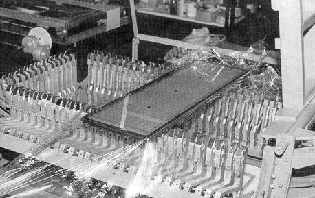
you can see it on the right of this picture. it also has a grey areas where either the spacer of the panel falls in or its just some foam of some sort so the foil is pushed against the panel all over (since its very importend to have good bond on the edge of a panel or it will make noises, this is hard on a flat hard surface when using such thin glue) then the center part rises up to the foil. panel is lowered and bonding can start.
might be even so that the center part rises up further and then the fingers just keep the same tension. they move up and backwards.
damn sophisticated. weights where way simpler in my opinion, but in production you dont want to open up 50 clambs.
you can see in this picture that the fingers are in relax stage and the hinges are folded more then when presure is apllied to the piston
The center part which you can see in this picture (the white bottom) goes up
you can see it on the right of this picture. it also has a grey areas where either the spacer of the panel falls in or its just some foam of some sort so the foil is pushed against the panel all over (since its very importend to have good bond on the edge of a panel or it will make noises, this is hard on a flat hard surface when using such thin glue) then the center part rises up to the foil. panel is lowered and bonding can start.
might be even so that the center part rises up further and then the fingers just keep the same tension. they move up and backwards.
damn sophisticated. weights where way simpler in my opinion, but in production you dont want to open up 50 clambs.
you can see in this picture that the fingers are in relax stage and the hinges are folded more then when presure is apllied to the piston
Last edited:
ok so after more thinking, the ingredient X for damping. sounds a bit vague. damping the membrane means adding mass, or mass by adding resistance in air (also mass , nylon fabric)
So the stuff thats on the back of the newer panels has a purpose but i dont believe its lying in the damping. i measured serveral panels my home brew and the original and they measure the same. only thing that keep happening is being the Res feq being lower of my panels. i stretch them as hard as i can. but they lower after a while. a few things that might happen here.
1. my mylar is not pre tensilized?
2. my glue is not hardened complete?
3. temperature in room lowers , so the air presure does as well... (would only be a thing in winter and during night, even then its to small)
4. My tire that stretches inflates during curing time ? (easy to test)
5. and this is on a limb, this coating on the backside is not only there for ""damping" but to give the mylar some more strength in the middle section (the biggest part of the membrane) so the foil wont relax as much after time. instead of the pre heated foil they used in the 57.
I can think of why they prefer brushing on some crap instead of putting every membrane (of the 8 present in one set) in an oven. TIME. time is money. they did not have 40 jigs and ovens. i can imagine adding the glue in the center maintain the tension better then having the foil relax on itself. back to the 50-55 hz mark instead of the 70hz i measure on every original panel. the part that relaxes is only the outer rim of about 1 cm near the spacers. so it will prob drop a bit but end up all the same. (and 1 cm does not expand as much as 18 cm)
Also the very nice clean finish on the holes on the membrane where the bolts go true might be a side affect because of there coating on the back. everyone used an solder iron (so did i) but holes are not as clean as the quad originals. even when using an template and a small tipped iron. they either used a round iron (foil as cylinder on an iron or any other heating device) or a cnc or the reason why the melting look so clean is the fact that there is a coating on the back of it. i dont have an old panels without this coating left to see if the holes are as good as the newer ones. (if someone does please confirm or dis confirm)
in my believe there are allot of false information on the quad panels mostly abused by people that sell refurbs. i've seen like a dozen of small company's that fix them with either 6 micron foil, re glue stators without re glueing the stator with the membrane (since you would have to destroy it to do it properly)
Using wrong coating, graphite,and others. (i am even thinking licron is not suitable, since i got panels that do drop, be it slightly like 0.5-1db db but they do drop, compared to panels that are 10 years old)
Further i have seen many threads where they show the old stretch jig and oven when it comes to Quad ESL63. this jig is for the 57 its clear, only pictures shown have a 57 pael on it all original pictures with 63 elements have the fingers jig. only one picture of the the original 57 jigg with a 63 stator on it is from musik wiedergaben , which they removed. They had a esl63 panel on top of the jig, but they only service 57's. also the 63 dont go in a oven as far as i know since the (finger jigg ) jigg wont allow it.
Last edited:
I don't know for sure what the mystery coating is, best guess would be an acrylic or polyurethane binder. It's purpose is not to damp the fundamental resonance of the diaphragm (ie motion of of the diaphragm back and forth in the gap). I think it is likely added to dampen the "crinkly" noises that mylar makes....at least that was a noticeable difference I heard when handling the diaphragm before and after peeling off the coating.
As far as I know, the ESL63 diaphragm is heat treated in an oven while under tension, just like the ESL57.
Read again the comments in the 1989 interview with Ross Walker. (from post#23)
One Thing Audio/Manufacturers/Quad/History/Peter Walker
excerpt...
"We stretch it up to the required tension and stick it in the oven. In its cold form, if you stretch it, it will creep. But by putting it in the oven under tension all the molecules will line up to the most stable position so the tension won't change. This is quite important because otherwise the resonance of the speaker would change and it is carefully designed to a particular value. If it was too slack it would hit the plates, too tight the resonance would be too high. Secret ingredient X is used as a damping layer on the Mylar and then we bond the frame to the electrode structure."
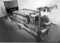
I haven't seen a picture of the ESL63 diaphragm stretching jig where you can definitely see the oven, but I did find one where you can see the wheels and rails leading to it.
As far as I know, the ESL63 diaphragm is heat treated in an oven while under tension, just like the ESL57.
Read again the comments in the 1989 interview with Ross Walker. (from post#23)
One Thing Audio/Manufacturers/Quad/History/Peter Walker
excerpt...
"We stretch it up to the required tension and stick it in the oven. In its cold form, if you stretch it, it will creep. But by putting it in the oven under tension all the molecules will line up to the most stable position so the tension won't change. This is quite important because otherwise the resonance of the speaker would change and it is carefully designed to a particular value. If it was too slack it would hit the plates, too tight the resonance would be too high. Secret ingredient X is used as a damping layer on the Mylar and then we bond the frame to the electrode structure."
I haven't seen a picture of the ESL63 diaphragm stretching jig where you can definitely see the oven, but I did find one where you can see the wheels and rails leading to it.
Attachments

Wow bolsert 🙂 i searched high and low for another picture of the jig, yeah i can see there is the track leading to the oven.. so they do heat treat, and the coating same as i thought is for wrinkling but only for the cutted hole, since there is no wrinling noise in a normal panel at all. i never heard any. also its not visible in the measurements.
btw bolsert do you have more of those pictures? or where did you find those? since my only info is from the pictures. and this is a verry nice and detailed one that can help us further.
btw bolsert do you have more of those pictures? or where did you find those? since my only info is from the pictures. and this is a verry nice and detailed one that can help us further.
this picture tells us there is an oven. and the template is used for the glue, and maybe the middle coating as well. since there is only one template. the glue end the magic x could be the same btw. you can see the glue trace on the foil. only thing we cant see if this is before heat or after heat. when she lowers the frame. if its before my guess is that the glue hardens faster in the oven, and maybe at the same time tempers the foil.
still its hard to see if the frame reaches the foil when its horizontal. does not look like it to be honest. since the part in the rear of the picture of the stator should almost touch it already.
damn what a nifty machine, i cant hardly believe everyone that refurb these panels do it right there is much more to it then meets the eye
its so funny these 2 hooks where not visible in the other pictures, same goes for the track/oven (although not seen here as well but it looks like the same principle as the older 57 jigg). i must keep in mind not to draw conclusions to fast myself 🙂 bad bad ...... i fell for it myself 🙂
Last edited:
Would you believe....on the QUAD company website! 😀Wow bolsert 🙂 i searched high and low for another picture of the jig...where did you find those?
About half-way down the page here:
ESL | QUAD | the closest approach to the original sound
- Status
- Not open for further replies.
- Home
- Loudspeakers
- Planars & Exotics
- Quad Mylar thickness, does not look like 3 micron!