Well back to square one I cant figure out how the fingers work, old theory is out of the window partly since there is no hinge in the L shaped aluminum only hinge there is from the finger closing... Ofc it does not really mater. Key is even tension , the old jig was simpler but had a few flaws compared to this one. Less clamps, chunkie big, no method of opening up all those clamps at once. So you had to fidl in the Mylar one clamp at the time. After tension Mylar goes in oven , then the special coating and glue is applied and frames lowerd. But what happens then remains a mystery
Still the frame and Mylar could go in at the same time but I'm not sure how well the stator likes these temperatures. As far as I know epoxy pcb does not like 150 degree c, wich is needed for the Mylar to relax
Still the frame and Mylar could go in at the same time but I'm not sure how well the stator likes these temperatures. As far as I know epoxy pcb does not like 150 degree c, wich is needed for the Mylar to relax
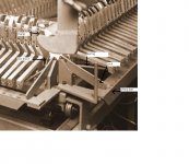
It would be nice to understand how the Quad jig worked. Attached is an image with some parts labled from what I can see the spring applies tension to the arm with the clamp attached, to release the tension on the arm the lifting bar is raised by the air operated ram shown in the full image. The lock holds the bar in place as the hole jig is rolled forward with the rams in the dropped position. The clamp holds the upper part in place with the stator attached. It is not yet obvious how the clamp fingers operate or how the film is inserted.
Stuart
Stuart
Attachments
Here is a link to a PDF containing an other photo of a jig but it is not obvious if this one moves, also the template on the left is not for adhesive, there is one stator on the film and one on the holder perhaps it is only a publicity shot and not representative of the production process, I dont read Dutch so dont know what the text says
Stuart
Stuart
i can see the ram and well its not clear but that could be springs indeed. but only weird thing is this would result in pulling backwards on the mylar but as well pulling it down. because its pivots. upping the ramp would be the relax state shown in the picture with the panel on top.
looking forward for the pdf 🙂
looking forward for the pdf 🙂
its pretty hard with springs. i mean the applied force depends on how far it is extended. i mean they have starting position when the ramp is upped. but when the foil is not equally positioned in the clamps,the ones that have longer foil from one finger to the opposite finger(for instance when the foil has some wrinkles) then applies less force on the foil then the ones where the foil is slightly stretched when positioned in the fingers.
with the weights the force is always the same.
here a limited spring spec sheet from springs on ebay
Item Name: Helical extension hook spring
Item Weight: 1.6g (0.056 oz) / one spring
Item Size: 6 x 38mm (0.236 x 1.496'')
Material: Steel
Wire Thickness: 0.5 mm (0.0196'')
Winding: 59
Extension: 200g (7.0oz) -> 55 mm (2.16'')
300g (10.5oz) -> 72 mm (2.83'')
so it extends 17 mm with each 100gramms added (wont be perfect linear either the first 200 grams is needed to pull it 17mm and after that one another 100 gram to move it also 17mm)
but if so lets say at one point the mylar has 17 mm more slack because its not perfectly put into the fingers (something impossible to do perfect)
then there is 100 grams less pulling force. ... i might be completely wrong here. but what you would look for is a constant pull on the mylar, starting from when its complete flat(pulling the slack out would not cost any force) , then add the pull force to achieve the tension you want.
Last edited:

You can see here that the right side apparently the mylar was either shorter or put in nicely without wrinkles because the left side extended further down. i can only think of that on the right side also more force is applied if i look at the spring specs , its more extended then the left side so also more force is applied
THis is the link to PDF
http://www.transtec.nl/downloadConnector.php?filepath=QUAD_ESL_2010.pdf
If you look at the gap between the the lifting bar and the ends if the fingers it is fairly even all the way along so the tension in each spring will be similar. I think the film would be attached with the rams up and the springs extended to there maximum. the rams would then be retracted and the arms would be pulled back by the springs streaching the film. The lifting bars would be locked in place by pulling the verticle handle to the left. The unit would then be rolled into the oven to heat the film under tension then removed, the film would quickly cool then the stator would be glued in place probably clamped against some sort of table raised from below.
Stuart
Stil even if the springes are fully extended there would be a difference in tension between them , as in my picture you can see clearly that one finger is further down then the other. Ofcourse this is what you want to stretch even . But because it's a spring that has more pull when fully extended versus half extended. It not a constant of let's say pull of 1 kg but depending on how far a spring is extended.
The pdf shows that that template is for there secret x coating 🙂 the contour does not match the frame outer dimensions and form. So indeed cant be for glue.
About the second frame in the picture my guess iTS the next one?!
The whole arm is to line up the panel with the coating on the foil so this panel must be glued or it would screw up the alignment
Last edited:
cant get my head around the fingers closing mechanics , looked at all pictures for hours. just not enough detail to see what actually happening. might come up with something of my own with a few magnets, and no springs but weights. but without the pulleys , since that makes it expensive. sort of the same L shaped forms like the fingers but a slightly longer arm will ensure a much lower weight is needed. so you can have many fingers. also the L shaped thing makes the use of linear rails for all tha clamps not needed. a pivot action is way cheaper then a linear motion. 🙂 if you can live with the fact that the foil will end up lower then when you put the foil in the relax state, nothing a lift underneath cant solve.
- Status
- Not open for further replies.
- Home
- Loudspeakers
- Planars & Exotics
- Quad Mylar thickness, does not look like 3 micron!