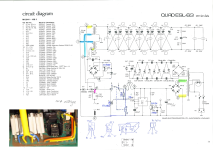
Never mind- I see what the bridge does. The 32x 220V Zener diodes in series with the LED will conduct and clip the HV signal from the transformers if the voltage gets too high (32 x 220V ~ 7 kV). I suppose the LED is there for test purposes to verify that the clamp is working.
Last edited:
If memory serves (I'm away right now) I've seen a unit with a light pipe on that LED that exits at the rear panel.
Still not very convenient to check of course.
I second Mark's view above. If there is a line connecting all the various versions of the '63 that appeared over the years it was almost always related to protection issues. It seems they really never mastered that.
Jan
Still not very convenient to check of course.
I second Mark's view above. If there is a line connecting all the various versions of the '63 that appeared over the years it was almost always related to protection issues. It seems they really never mastered that.
Jan
I have a tube amp that clips at 50W in 8 ohms but it is designed to drive down to 2ohms load. All amplifiers that is designed for <50W in 8 Ohms would work with no protection circuit.
Stripped my 63s from clamp board and R/C link.
Remember that when we have capacitors and inductors we need resistive elements, they are our best friend damping.
I showed my speaker cables after a listening demo. And a guy saw my "telephone line" 32AWG (0.2sq mm) speaker cables connected to the 15" dipole woofers lot of comments and discussion about cables!
The comment was that if i changed the cable to a thicker one, the sound would be much better.😊
Told him about the series resistors of several ohms in series with the woofers to adjust the Q values....
As long as the plastic insulation is not melting while playing im fine. Yes I enjoy the speaker cable discussions soo much.
BTW, I have here in front of me an ESL63 input module that has a 12V Omron relay on it! (Omron G2E-182P-M). Seems the (edit🙂) coil is between the anode of a TIC216M and ground. Maybe I should trace it out.
Jan
Jan
Last edited:
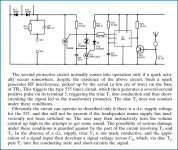
The original ESL63 protection circuit included some parts (T2, T3, C26) to ensure the Triac T1 crowbar was triggered if the speaker was over driven even if the AC power was turned off.
Here is Baxandall's description of the circuit:

The first I recall hearing of the relay was in a Stereophile review of the US Monitor version of the ESL63. I know there were issues with false triggering of the original circuit when there was noise on the AC line. Perhaps the relay was an effort to address this. Here is a schematic showing how it worked. Note that the relay contacts were hand drawn in a non-standard way. With AC power off, the relay contacts are closed and the crowbar will be triggered with audio input from the amplifier. Once AC power is applied the relay is energized and opens the contacts, so the Triac would only be triggered if a spark was detected.

In later versions of the ESL63, this protection feature(shorting the terminals if audio applied without AC power on) was removed altogether.
No doubt stokessd will have some additional details on the history.
Here is Baxandall's description of the circuit:

The first I recall hearing of the relay was in a Stereophile review of the US Monitor version of the ESL63. I know there were issues with false triggering of the original circuit when there was noise on the AC line. Perhaps the relay was an effort to address this. Here is a schematic showing how it worked. Note that the relay contacts were hand drawn in a non-standard way. With AC power off, the relay contacts are closed and the crowbar will be triggered with audio input from the amplifier. Once AC power is applied the relay is energized and opens the contacts, so the Triac would only be triggered if a spark was detected.

In later versions of the ESL63, this protection feature(shorting the terminals if audio applied without AC power on) was removed altogether.
No doubt stokessd will have some additional details on the history.
Yes that looks like my board, thanks!
BTW I have seen several different types of the electronics, but not yet the one with the resetable fuse.
Jan
BTW I have seen several different types of the electronics, but not yet the one with the resetable fuse.
Jan
Last edited:
I've got a few of those boards if you are looking for a matched set.
I looked through my ESL-63 literature and I don't have an official schematic for that board revision. I think it was fairly short lived and right before they went to the second triple stacked rectifier and zener string clamp board and the simplified RF clamp board pair.
Sheldon
I looked through my ESL-63 literature and I don't have an official schematic for that board revision. I think it was fairly short lived and right before they went to the second triple stacked rectifier and zener string clamp board and the simplified RF clamp board pair.
Sheldon
Last edited:
I've cloned those boards and a lot of times I just put in a wire jumper where the LED would go. Sometimes I put the LED in, I can't say i've ever used it when diagnosing a speaker.Never mind- I see what the bridge does. The 32x 220V Zener diodes in series with the LED will conduct and clip the HV signal from the transformers if the voltage gets too high (32 x 220V ~ 7 kV). I suppose the LED is there for test purposes to verify that the clamp is working.
Sheldon
When the Zeners are clamping the 7 kV signal, I wonder how much current is going to go through the LED. Apparently not much or they couldn't get away with using an LED there.
Did the resettable polyfuse appear when the clamp board was simplified?I looked through my ESL-63 literature and I don't have an official schematic for that board revision. I think it was fairly short lived and right before they went to the second triple stacked rectifier and zener string clamp board and the simplified RF clamp board pair.
If so, perhaps that explains the purpose of the fuse...to help protect the speaker from being over driven if the AC power is off.
You are correct that 3µm dust covers roll off the response with a 1st order LP trend. However, there are peaks and valleys superimposed on that trend caused by reflections between the diaphragm and the dust covers....I will continue to state that the dust cover acts like a first order low pass filter, with the corner frequency in the 25KHz region or higher. Any difference you see in those two plots are more about the grilles than the dust covers IMHO.
To illustrate this, here are measurements of my own ESL with NO dustcovers, and then without moving the mic I measured:
- dust cover on just the rear
- dust cover on just the front
- dust cover on front and rear
Normalizing the responses relative to the “without dust cover” response, and you can see the impact of the dust covers.
When octave smoothing is added, the 1st order LP behavior becomes apparent in the measurements for the front and both dust covers.
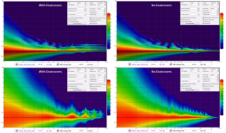
I had also previously posted spectrogram plots of these measurements where you can clearly see the multiple reflections showing up in the time domain and the peaks and valleys in the frequency domain.
https://www.diyaudio.com/community/threads/esl-high-frequency-chaotic-modes.382598/post-6939879
- left side is with dustcovers, right side without
- top is 1/3 oct wavelets (more time resolution), bottom is 1/12 oct wavelets (more frequency resolution)

Note that this is all happening in the first 1mS, so you would have to change the settings for your spectral decay plot to see anything.
If you want, you can send me a copy of your impulse data and I could generate similar plots for your ESL63 measurements.
wout31 had posted a similar spectrogram for his ESL63 showing the dust cover reflections, however I’m not sure what settings were used for the plot generation.
https://www.diyaudio.com/community/threads/esl-high-frequency-chaotic-modes.382598/post-6939338
Thanks for this Steve. These are exactly the artifacts I saw doing 'waterfalls' [1] circa 1980 with my early ESL 63.You are correct that 3µm dust covers roll off the response with a 1st order LP trend. However, there are peaks and valleys superimposed on that trend caused by reflections between the diaphragm and the dust covers.
To illustrate this, here are measurements of my own ESL with NO dustcovers, and then without moving the mic I measured: .... Note that this is all happening in the first 1mS, so you would have to change the settings for your spectral decay plot to see anything.
As you say, the important stuff is happening in the first ms. I think I have that 'waterfall' [1] somewhere under a load of diving and boating junk.
[1] actually a PAFplot after Peter Fryer. 'Waterfalls' where KEFplots and there were JAPplots too but I can't remember the Japanese company.
I have been running mine without dustcovers since the 90ties.... depends on the cleanliness "inna da hause" I guess
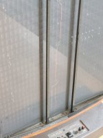
Same here no dust covers or grilles, 'socks' are now steel frames held on with magnets for easy removal. Naked for four years with no UV or dust damage.
The ML ESL's have no dustcovers and advise occasional vacuuming which is what I do with mine.
... there are peaks and valleys superimposed on that trend caused by reflections between the diaphragm and the dust covers ...
And before in 2022:
... The HF reflections seen in the upper-left plot are 0.156mS, 0.309mS, 0.477mS, 0.630mS, and 0.783mS after the primary impulse arrival.
These are all multiples of roughly 54mm which is nearly exactly twice the spacing of the dustcovers from diaphragm in my test ...
It might be a nice little project to set up a FIR filter reproducing this reflective pattern, and then compare AxB along with headphones. I think it might not be very hard to do so.
@ Bolserst: Do you still have the original file of the 2022 "naked" measurement handy? Might be a starting point if so.
Ha! I was just thinking about that this morning...wondering if anybody would be interested.
I'll see if I can dig up the measurements, or as a fall back use the modeled response which matched measured response quite well.
Any preference on the sampling rate and for the FIR filter?
I guess I can just post a 48kHz and 96kHz for people to play with...those are the most common.
I'll see if I can dig up the measurements, or as a fall back use the modeled response which matched measured response quite well.
Any preference on the sampling rate and for the FIR filter?
I guess I can just post a 48kHz and 96kHz for people to play with...those are the most common.
If you also find the "dust-covered" file it might be useful to post it along the "naked" one. To perform some kind of DSP math like
"dust-covered" - "naked" = "filter"
"dust-covered" - "naked" = "filter"
Any preference on the sampling rate and for the FIR filter
Addendum: SR @ 96kHz files would be appropriate, so we can compare results with your graphs in post 92. For audibility test then we can easily downsample the filters.
I summarized the original blog post on restoring the speakers that had a lot of stuff I tried that didn't work. The summary is here.
- Home
- Loudspeakers
- Planars & Exotics
- QUAD ESL-63 rebuild
