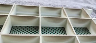
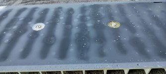
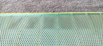
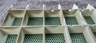
I also occasionally see dog pee on the grille cloth, grilles and dust covers. Don't underestimate the utility of the dust covers as a "raincoat"
Sheldon
Sheldon
I have been unable to locate the measured impulse files I would need to create FIR filter directly from my measurements.It might be a nice little project to set up a FIR filter reproducing this reflective pattern, and then compare AxB along with headphones. I think it might not be very hard to do so.
@ Bolserst: Do you still have the original file of the 2022 "naked" measurement handy? Might be a starting point if so.
But, we can still do the next best thing and use analytical results since they match reality quite well.
I'd like to make them as close to the ESL63 as I can.
@stokessd, can you tell me the spacing between the dust covers and the stators? is it the same for front and rear?
Would it be possible to get 3 near-field measurements, before and then after each dust cover is applied?If you guys want measurements, I can do that next pair of 63's I'm working on. You tell me what you want and I'll do my best to provide it.
You could position microphone a set distance that would be close to the dust cover plain centered on a particular opening in the stiffener grid.
My experience is that the response looks weird if you measure close. It gets better >20cm from the speaker. (Should be close enough)
A slightly different but related question. I am modifying a pair of ESL 63's (the ESL 31.5 as described elsewhere).
Waking up this morning, I thought, if I limit the low frequencies on the rebuilds to 200Hz, I could increase the stator-stator spacing a bit for more excursion and SPL. Thoughts?
Jan
Waking up this morning, I thought, if I limit the low frequencies on the rebuilds to 200Hz, I could increase the stator-stator spacing a bit for more excursion and SPL. Thoughts?
Jan
I have had the same thought but opposite!
Reading Baxandall and his thought of increasing the capacitance of the transducer to get a more favourable relation to stray capacitances by decreasing the distance on the mid panels (and lower the bias). The distortion would be lower... 🙂 always two sides of the coin.
Reading Baxandall and his thought of increasing the capacitance of the transducer to get a more favourable relation to stray capacitances by decreasing the distance on the mid panels (and lower the bias). The distortion would be lower... 🙂 always two sides of the coin.
The center panel of the Quad ESL57 is said to be one of the best midranges ever built. It comes along with a very narrow stator-to-stator distance.
Yes indeed. But the stray capacitances figures in the efficiency but not the distortion I thought.I have had the same thought but opposite!
Reading Baxandall and his thought of increasing the capacitance of the transducer to get a more favourable relation to stray capacitances by decreasing the distance on the mid panels (and lower the bias). The distortion would be lower... 🙂 always two sides of the coin.
As I understand it, smaller distance between stators only lowers distortion because it limits excursion and distortion is depending on excursion. I don't think that stator-stator distance in itself figures in distortion. Or am I wrong?
Jan
Most stray capacitance is probably in the transformers, and I just forgot that Jan has solved that issue already.... my bad.
I just listened to Patricia Barber singing Ode to Billy Joe on the rebuilt Quads and recorded it with a binaural mic and PCM-M10 recorder. Here's the file right out of the recorder. I don't know what the mic's response is in my configuration, but it seems a bit bass heavy. Otherwise, not too bad. You might hear some extraneous noises- I live in an urban environment that's rarely quiet.
Nice Mark, I hadn't heard this song before from Patricia B.
Very clean transients, high resolution, indeed a bit bass heavy overall, but nothing a little EQ can't fix.
Jan
Very clean transients, high resolution, indeed a bit bass heavy overall, but nothing a little EQ can't fix.
Jan
if I limit the low frequencies on the rebuilds to 200Hz, I could increase the stator-stator spacing a bit for more excursion and SPL. Thoughts?
For a properly operating constant charge ESL, the force should be linear for diaphragm excursion anywhere between the stators. At very low frequencies it may get harder to maintain the charge time constant necessary, or the transformers may start to saturate (more common in my experience). Of course you could just run out of excursion at high enough SPL as well.smaller distance between stators only lowers distortion because it limits excursion and distortion is depending on excursion.
Sorry if I'm misunderstanding what you're getting at, but this thread has a pretty good rundown of what goes on in various modes of operation:
www.diyaudio.com/community/threads/i-always-wanted-to-ask-why-bias-voltage-on-esl.240464/
As @esl 63 pointed out, most come at this from the opposite direction: roll off the low frequencies so lower spacing can be used (because lower excursion is needed), so voltage sensitivity increases, and transformer selection is easier. At very small spacing you also get some benefit from the breakdown voltage per mm of air increasing. Of course decreasing spacing with something like a Quad panel has challenges since you don't have control of the diaphragm free span like you would if making your own panel and the spacers are part of the overall structure.
I would come from the other direction: maintain or increase the spacing for higher SPL.As @esl 63 pointed out, most come at this from the opposite direction: roll off the low frequencies so lower spacing can be used
Jan
My serial numbers are 12485 and 12486, so older than yours. This site says mine were made in 83 or 84, yours in 88 or 89. Maybe they changed the diaphragms/coatings somewhere between mine and yours.@ Mark Rehorst: Ok, now I am close to them: SN 023809 and SN 023810
Last edited:
- Home
- Loudspeakers
- Planars & Exotics
- QUAD ESL-63 rebuild


