I'd bet the problem is a diode rather than a cap (you are measuring them in parallel essentially, right?). I'd replace them first. You can just ignore the wax and solder in new diodes, it will melt away from your solder region. It's a mess to work with. I recoat when I'm done.
that might be very true. components ordered, will let you know. I also ordered parts for that HV probe referenced in the other thread, and it occured to me that the board could actually be tested outside of the speaker, on the bench, with an isolation transformer, to check if it works before putting it back in.
Those two screws that hold the board either needs special equipment or me breaking my fingers 😀
Those two screws that hold the board either needs special equipment or me breaking my fingers 😀
Yes, you can run it on a lower voltage as well so you don't shock the cookies out of yourself quite so bad.
As for removing the boards, you can unscrew the metal interface panel and pivot it upwards. Another option is something like this:
https://www.amazon.com/Xcelite-5-Piece-Midget-Ratchet-Screwdriver/dp/B001T4VY3I
Sheldon
As for removing the boards, you can unscrew the metal interface panel and pivot it upwards. Another option is something like this:
https://www.amazon.com/Xcelite-5-Piece-Midget-Ratchet-Screwdriver/dp/B001T4VY3I
Sheldon
thanks for the link to that tool, haven't seen that one before! and thanks for the warning, have been in power electronics professionally for 30 years now and still got all my cookies intact, so I hope these speakers won't change that 😀
I have a small 90deg bent screw driver (double L shaped) with philips and flat on either side. I replaced all those screws with 3mm x 10mm hex heads which solved the issue. Once you loosen them they can use your fingers to spin them out. Would that ratchet not be too wide to get above the screw head?
kffern
kffern
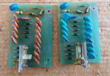
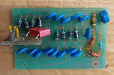
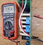
Repair done, listening test will be tonight. I did find some interesting things though. Pictures attached show the two cascades in their original state, and the single one is after rework. They do not look as nice as before but measure ok - with my HV probe, I measured 4.01kV on the output (my probe is not verified yet to work correctly, though, so the values may be off - I take it as a proof that high voltage is present ).
Interesting that both PCBs used very different capacitors, and they apparently also aged differently over time. Out of curiosity, I measured all the components, and the blue caps were all consistently down to 6.9...7.5nF. The brown caps were all over the place, between 6.5nF ...12.5nF (sorry, I could not measure leakage current or breakdown voltage). But the lower capacity indicates also lower cascade output voltage for a certain load, which in the case of an ELS should not not have any leakage current after charging up - should not..... 😀
The resistors seemed to heat up quite a bit in operation, and around them the wax was completely gone. The PCBs were a little bit discoloured as well, but not heavily.
Thanks for asking, the diodes seemed fishy, they all similarly measured a forward voltage of 1.35V, again no leakage current or breakdown voltage could be measured. A new diode (Semikron SKA1/17) measures 0,635V at 5mA, as you would expect. And, while I was at it, I also replaced the 1000uF cap on the other board, here the old caps measured 950uF or so.
Very interested in the listening test now, will report later today.
Attachments
The front end of that board does get pretty warm. When I replace those parts, I use higher wattage resistors and I also space them off the board a bit for better cooling.
Sheldon
Sheldon
OK, listening test done - everything is back to normal, working fine. Obviously that was the problem. Thanks a lot to Sheldon and kffern for your help!
(back to music now... 😀)
(back to music now... 😀)

well well, unfortunately the problem re-appeared. It was good for a while, then intermittent (when the right speaker was operating a while at some point it worked fine), and now it is consistently lower volume. It seems that high frequencies (eg voices) are fine, but anything lower is more and more to the other side of the stage, and most volume really only comes from the left speaker.
Tried to listen to the individual panels, and the middle part of the speaker seems to work fine, while there is pretty much no output at the top and bottom (or very little). This would indicate to me that one or some of the inductors are broken. Last time I tried to measure with a 1kHz pilot tone, and could measure output at each stage of the delay line, and similar values at both speakers, but I have not tried to do this now (guess I picked a moment when it worked, or I just pushed the loose ends togehter....)
In any case, the transformers and HV supply are working fine, and the panels have been remade in 2019, so that really limits it to the delay line. Do you know if those inductors can still be obtained somewhere, or maybe the complete PCB? I think I would replace them in both speakers, while I am at it....
thanks in advance for your help!
That is a very tricky conclusion.the panels have been remade in 2019, so that really limits it to the delay line
Wouldn't be the first where panels start having problems again after a short while.
well, well..... I am disassembling the delay line board tomorrow, since Jan D kindly offered to send me another coil, and so we should know soon.
I've had coils go bad, on a few occasions. It's often an intermittent connection within the coil and it triggers the clamp circuit. maddening.
But I agree, it's the panels 99 times out of 100.
Sheldon
But I agree, it's the panels 99 times out of 100.
Sheldon
Highest current is in the first coil and on the 989 and 12 models.
Tested a 8 panel variant and no problems with the coils though.
I say it again.... active filter at 80-140hz and dipole subwoofers, gives you:
Tested a 8 panel variant and no problems with the coils though.
I say it again.... active filter at 80-140hz and dipole subwoofers, gives you:
- up to 10dB higher dynamic range and higher output.
- 1 octave deeper bass (or more..)
- less stress on the membranes, better reliability
- less membrane movement and less risk for discharge between membrane and stator, gives less stress on clamping elecronics and bias electronic
- less currents in the coils
- less distortion and more "roomines" (deeper bass)
More measurements done....
I disassembled the speaker and checked all the wiring with an ohmmeter, all fine, everything connected. Also, no short-circuits between the signals and also to the HV line.
Next I checked the HV arriving at every panel with my HV probe, all fine and identical (~4kV)
Then I checked the AC voltage on all panels with an Audio signal, and there was a good signal at every contact, both sides (~30V AC for the inner panels, ~24V AC on the bass panels, with ~0.3V AC input). All the while, all panels were working except the top one (I could hear nice bass output at the bottom panel and mid/high at the two inner panels, nothing on the top panel).
Then I checked the capacitance of all panels, and all the inner connections measured ~50pF to the HV line, all outer (bass panel ) connections were around 108pF, all in range as expected.
In conclusion, all panels are connected fine and playing, including the top one, and capacitance is ok, so whats wrong? Scratching my head here...... Unless somebody has a good idea, I am left with shipping the whole thing back to my refurbisher...
- Home
- Loudspeakers
- Planars & Exotics
- QUAD ESL-63 diy repair