Its difference enough that it will cause a small offset but you can try it... just unsolder the end of R5 from the opamp and connect it to the input ground instead. Or just link across R6. The opamp won't mind and the power supply to it is severely limited anyway.
Difficult...
Fit a bulb tester and use the tried and tested "technician approach" (honestly). Touch, stroke and probe the solder side of the PCB around the various stages gently with a finger. See where doing that changes anything. You might get a feel for where things are going wrong... you might find a finger on the base of some transistor stops it completely.
Cautionary warning... some devices will have the full rail voltage across them so be aware ! 😀
Honestly though... its a technique used by many techs... just be careful.
Sorry for late one. I will write down some things which might be of some help.
My 606/909 also used to oscillate but I manage to cure it.
First of all you need proper psu. Nice capacitor bank and proper wiring.
Install some 100n from each line to the ground. Do the same on boards also.
Everything must be attached to the heatsink which must be grounded.
My guess is after that you still need to install 1n across T12(b-c)
There is also possible something is going on at ''positive side''. Try to change the value of R7.
I've also tried with some 100p across T7(b-c)
There is also R8,C4 network which could be modified. R8 is ''value subject to change''
But first of all make sure both channels are similar as much as possible. Mechanical factor is also important. After that you will hopefully get similar readings (flat line). Fingers crossed.
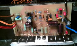
Here is how looked my board at the end.
Cheers
My 606/909 also used to oscillate but I manage to cure it.
First of all you need proper psu. Nice capacitor bank and proper wiring.
Install some 100n from each line to the ground. Do the same on boards also.
Everything must be attached to the heatsink which must be grounded.
My guess is after that you still need to install 1n across T12(b-c)
There is also possible something is going on at ''positive side''. Try to change the value of R7.
I've also tried with some 100p across T7(b-c)
There is also R8,C4 network which could be modified. R8 is ''value subject to change''
But first of all make sure both channels are similar as much as possible. Mechanical factor is also important. After that you will hopefully get similar readings (flat line). Fingers crossed.
Here is how looked my board at the end.
Cheers
Attachments
It could be as simple as the PSU wiring is too long. During testing both amps do have long PSU wires albeit heavy duty wiring. Odd that only one channel is exhibiting this problem. It's horrible out today so I'm not going to sit in the garage and play today.
I just CANNOT get this second amplifier to stop oscillating, neither can I transfer the fault to the working channel ??
Anyone fancy me posting it to them to have a try ?
Anyone fancy me posting it to them to have a try ?
Hi Katie, Am no expert but have built a few of these and am in the throws of building 6 more, so happy to take a look at it if others on this forum (who have far more expertise than I) are unable to assist.
If you PM me we can exchange details and get something sorted
Cheers
Ed
If you PM me we can exchange details and get something sorted
Cheers
Ed
Only when I had it laid out as per one of the early posts in this thread- the one Sakis commented on, and then only because the large heatsinks were themselves not joined electrically. Earthing them cured that, however I then re-laid out the output transistors all on one U section and have not seen any further oscillations. I needed to do that anyway to fit 4 of them into the tight space I have in the chassis.
My guess is that you have a faulty component somewhere -when I worked on the production line at Marconi's it was not uncommon to find out of spec passives as well as active ones , e.g. I remember once finding a foil wound polyester cap that was acting like a diode.
My guess is that you have a faulty component somewhere -when I worked on the production line at Marconi's it was not uncommon to find out of spec passives as well as active ones , e.g. I remember once finding a foil wound polyester cap that was acting like a diode.
I'll give it one more go with everything fitted in the chassis to see if it is a grounding issue. Finding a defective passive is going to be a PITA.
In the meantime I'm also building some Burmester 933 clones. I'll start a new thread on how that goes.
You might want to take a look at this thread - not directly related to oscillation however it does indicate there were some issues with this design http://www.diyaudio.com/forums/solid-state/166885-quad-909-buzz-problem.html
Cheers Ed, I'll have a look. In the meantime I'm thinking about the bulldozer approach. Clamping each base to gnd with a hefty cap until I can get the oscillations to stop.
I've finally "moved in" so the Quad clone will start again. The aim is to reduce the experimental PSU (long) leads to minimum length then to try local decoupling. It's odd that one amp works perfectly and the other oscillates.
Don't know where to go after that ? Remove all the caps and test them for value, shunt every BE with a cap until the oscillation stops ?
Don't know where to go after that ? Remove all the caps and test them for value, shunt every BE with a cap until the oscillation stops ?
Well I managed to pick up a genuine Quad 606, recently recapped and serviced by Quad for £300. Anyone interested in trying to sort out the clone boards, I'm open to offers.
I've just bought a decent LCR meter, it'll be interesting to compare all the component values with the clone against the genuine article to find out why the clone oscillates.
- Home
- Amplifiers
- Solid State
- QUAD 909 Clone