It will be very interesting, waiting for the information. check the value of resistor R8 and capacitor C4
Silly question perhaps, but have you had a load connected and maybe compared levels and sensitivity of the oscillation at various points to track it down? Not that this is a good or totally safe strategy but desperation calls for desperate measures.
Desperation calls for unorthodox measures that is... 😉.....desperation calls for desperate measures.
I've just laid my hands on a genuine Quad 606, now with three out of four working channels I might be able to find what is wrong.
Hello every body, I'm french, sorry for my so bad english (thanks Google translate.....😀)
So, I order two PCB and components in China (ebay), I bought transistors and selfs in France.
I specify, i've not oscilloscope, only multimeter and soldering iron (i'm not sure for this last word).
I put this cards into a PMA-1560, channels power were out of order.
I change transformer for a 2 x 60V (PMA-1060 transformer, in fact)
One symmetrical supply (no floating mass, scoop...... 😉)
It is not the problem.
When i start testing (it's more strong to explain, now, but, i try), the sound seems saturate, some vibrations. First time, i don't understand, each component seems OK.
I've replace power transistors by 2N3773, and T7/T8 by TIP42C. One moment, i decide to change this last transistors by another TIP42C, and after this, it was OK.
On the other channel, i've the same problem, i've test a lot of another transistors (2SB945, MJE15031, even RCA 40872 from a Quad 405). This channel, now, run with a BD244C.
So someone is able to tell me what happen?
It is a problem with transistor gain (HFE)?
A problem with conception of transistor? (NOS, new transistor, made in china???....😕)
Waiting, i hope it is not so hard to read me.
Kind regards,
Samuel.
I bought these PCB's one works fine the other oscillates, obviously a component issue but these aren't easy to clone.
I had a similar experience building a Quad 606 clone and yes, I believe the oscillation (both channels) was due to using modern substitutes for the original RCA driver transistors and also, the recently manufactured power transistors, even though they are still genuine 2N3773 types. I understand from other contributors, that none of the transistors manufactured now will be identical to those originally specified. In particular, the increased Ft (gain-bandwidth product) now available in the output stage increases the probability of high frequency instability, as you suspect.So someone is able to tell me what happen?
It is a problem with transistor gain (HFE)?
A problem with conception of transistor? (NOS, new transistor, made in china???....
Usually, we think higher performance parts must lead to better audio performance but here and in many DIY projects discussed on the forum, we find oscillation effects that did not often occur with the older parts they were based on. My solution was to select low Hfe transistors from a larger batch. It was an expensive solution but at least the amplifiers worked reliably for me and the guy I sold it to.
BTW, your Google translated English is fine and understandable.
Thanks for your reply. I use google translate only for 10%... 🙄
I bought the 2N3773 in Electronic shop, in France, on internet.
This 2N3773 are made by "PMC". I imagine there was better manufacturer, but more expensive. One part: 2.50€.
It is not really expensive for start one experience. Now, the amplifier works really well. Sound is really unique.
I drive Ditton 66, and it is the first amplifier who drive so well this speakers.
I begin the experience with a Quad 405, and I feel a good potential.
But, a Quad 606, same used is very expensive.
Thanks a lot for your experience.
Hello guys
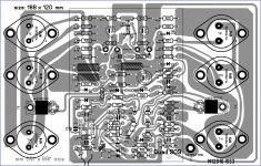
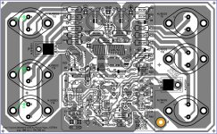
I was reading here and there and I decide to give a try and make a layout from some images that were posted here, here is the Quad 909 the layout is about 120 mm x 188 mm this might not be as accurate as the original one but I decide to post it here please if some one that know well the design can check for errors or possible modification that I do not know about it I will really appreciated any help, I'm just a layout fanatic and I love what I do, I also simulated the circuit in multisim and I think responds really well I mean I'm not an expert but I know the circuit will behave correctly the only components I was not able to place on the simulation is CR1 LM334 and CR2 J503 what I use on the simulation for CR2 is 1N4148 it does work but I think should be there a 500uA controlled current and for CR1 I use a fix resistor "not correct" but I didn't have a choice 😛
question: the secondaries of the transformers is 82V right ?
Regards
Juan
Attachments
Last edited:
82-0-82Vac sounds far too high.
82Vac centre tapped is a more reasonable 41-0-41Vac
That would give supplies around +-60Vdc and good for around 150W to 170W into 8ohms.
Even +-82Vdc sounds too high.
82Vac centre tapped is a more reasonable 41-0-41Vac
That would give supplies around +-60Vdc and good for around 150W to 170W into 8ohms.
Even +-82Vdc sounds too high.
oh so center tapped can be use ? I thought was not possible because of T15 and T16 virtual GND circuit uhmmm ? interesting, I will check that out on the simulation
If you are cloning Quad's virtual ground, then you don't need two secondaries, not even a centre tapped secondary.question: the secondaries of the transformers is 82V right ?
A single secondary is what your NEED.
Both a centre tapped and a dual secondary can be converted to a single secondary.
roger that Andrew,
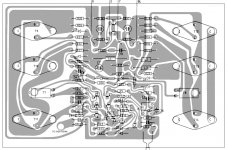
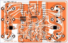
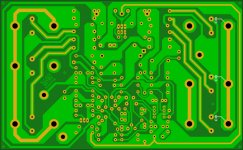
I will leave a file Sprint 6 here if some one need to make a clone of the Quad 909 "not to be commercialized please" only to diy and learn about this current dumping design, from the data that was post here I was able to re-clone the PCB but to let you know it might not be as accurate as to fit the original heat sink so the heat sink has to be made for this clone PCB unless holes of the TO-3 are enlarged to have some sort of game tweaking but not recommended I think 🙂 on the grey layout image what I did is flip the image so I will have a top view of the components then I used a back wall on Sprint file then I begin from there making the components from scratch and then I place the copper traces little bit at the time I spend probably 3 day 🙂 doing this well I hope some one check this for bugs please if any error you might see feel free to post it here I do not mind at all 😉
Best Regards
Juan
Attachments
Last edited:
Hi Guys,
I built the Quad 606 from files Juan sent me. I am seeing some oscillation at about 3Mhz. The output inductor is getting very hot. I made some part substitutions based on what I had on hand. These may be causing it so I thought I would come here and ask. If I should start a new thread let me know and I will.
These are the substitutions I made.
2n5551 for MPSA43
2n5401 for MPSA93
BC550 for BC413
BC560 for BC214
MJE15031 for 40872
MJ21194 for 17556
E-701 for J503
I know that is a lot of changes and I probably shouldn't expect it to work but I'm hoping some of you who have built these can tell me if I am at least on the right track.
Thanks, Terry
Try 1n foil capacitor across T12,T13,T14 (base-collector). One capacitor for whole group. It helped at my clone. Check output zobel C10,R33. Check all grounding. Are both channels the same? I mean oscillation?
Cheers
Cheers
Ah.one more thing. MJE15031 might be too fast. Try something slower like BD244. I would generally recommend nice old and slow transistors here. Also T5 and T6..high hfe and really fast transistors will cause trouble.
One more thing crossed my mind. Do you have grounded heatsink?
Best Regards
One more thing crossed my mind. Do you have grounded heatsink?
Best Regards
Try 1n foil capacitor across T12,T13,T14 (base-collector). One capacitor for whole group. It helped at my clone. Check output zobel C10,R33. Check all grounding. Are both channels the same? I mean oscillation?
Cheers
so it will look like this image sir ? 🙂
Attachments
Last edited:
No no...just one for all three transistors. It helped at my case but it won't necessary at Terry's. I must admit that 606 is one of most problematic amplifiers I tries to clone...really nasty oscillating amp. But also one of the very best sounding. It is really really nice one.
One thing is really important or at least it was in my case. Proper grounding. Heat sink must be grunded. Don't try 2 sinks, one for each group of outputs without attaching together.
But again. It is just my experience.
Cheers
One thing is really important or at least it was in my case. Proper grounding. Heat sink must be grunded. Don't try 2 sinks, one for each group of outputs without attaching together.
But again. It is just my experience.
Cheers
No no...just one for all three transistors. It helped at my case but it won't necessary at Terry's. I must admit that 606 is one of most problematic amplifiers I tries to clone...really nasty oscillating amp. But also one of the very best sounding. It is really really nice one.
One thing is really important or at least it was in my case. Proper grounding. Heat sink must be grunded. Don't try 2 sinks, one for each group of outputs without attaching together.
But again. It is just my experience.
Cheers
oh ! I see now, only one 1nF cap for all 3 power transistors got it 🙂
so all heat sink "if separated need to be linked grounded"
- Home
- Amplifiers
- Solid State
- QUAD 909 Clone