I'm moving house this weekend, I'll try and get back to it once I'm settled.
TR7 and TR8 do struggle to make a good connection with the board as their legs aren't long enough.
TR7 and TR8 do struggle to make a good connection with the board as their legs aren't long enough.
Nearly two weeks after moving and I'm just discovering my precious projects amongst the boxes.
Next step is to get some workshop benches for the garage.
Hopefully next week I'll be able to do some comparison tests between the two amps.
Next step is to get some workshop benches for the garage.
Hopefully next week I'll be able to do some comparison tests between the two amps.
Well it didn't take too long to discover that the +6V8 supply to the op-amp is missing. Next job is to find out why. Maybe a duff D12. Yes it is in the right way around, well according to its markings anyway.
Last edited:
Well, now I've had time to look over the schematics this should be fairly easy.
The +6.8V is only used by the op-amp so it can only be either:-
1. Wrong value R41
2. Defective IC1
3. Defective D12
4. Poor joint or track shorted somewhere.
Shouldn't take too long to find.
The +6.8V is only used by the op-amp so it can only be either:-
1. Wrong value R41
2. Defective IC1
3. Defective D12
4. Poor joint or track shorted somewhere.
Shouldn't take too long to find.
Could be a problem around the input stage with the opamp trying to deliver more current than its 10k supply feed can deliver. That would be the most likely imo.
Possibly but the output resistors on the op-amp should limit any fault current.
First step will be to remove op-amp (it's in a socket) and see what I can measure.
The amp does sort of work but it's distorting heavily.
First step will be to remove op-amp (it's in a socket) and see what I can measure.
The amp does sort of work but it's distorting heavily.
Yes, but its only got a few ma available to it from the supply (10k and zener). That's the limiting factor here, not the opamp current limit.
The +6.8V was down to about 2.7V, that means something was pulling about 4.8mA through the 10K resistor ?
I'm asking myself the same question.
I did buy the OPA???? upgrade op-amps but might have fitted OPA624 during testing.
I'm at work at the moment so I might have got that number wrong.
I did buy the OPA???? upgrade op-amps but might have fitted OPA624 during testing.
I'm at work at the moment so I might have got that number wrong.
It needs to be a FET opamp. If it draws to much current then just scale the 10k to suit such that there is always a couple of milliamps in the zener. The TL071 can be as good as any for this application.
I can certainly test the op-amp off the board for it's quiescent current. But, initially I'll carefully check that all the right parts are fitted.
OK, home from work.
The recommended upgrade for the Quad is the pricey OPA627AP, which I bought.
With the OPA627 in the board the +6.8V is down to a mere 2.6V, I can't see any oscillations and the +/- inputs are as close to 0V as I can measure but the output is over 1V, probably limited by the low V+.
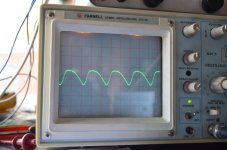
Now, I've swapped in the cheaper OPA604AP and everything is as it should be, I haven't tried a signal through it yet, that will be the next step.
The other channel is working fine with the OPA627 ???
The recommended upgrade for the Quad is the pricey OPA627AP, which I bought.
With the OPA627 in the board the +6.8V is down to a mere 2.6V, I can't see any oscillations and the +/- inputs are as close to 0V as I can measure but the output is over 1V, probably limited by the low V+.
Now, I've swapped in the cheaper OPA604AP and everything is as it should be, I haven't tried a signal through it yet, that will be the next step.
The other channel is working fine with the OPA627 ???
The board design is probably OK as one channel works and it is a clone of the original.
I really don't know where to start to find the cause of the oscillating.
I really don't know where to start to find the cause of the oscillating.
I notice that my board has an unmarked component position between T1 base and T3 emitter, I'm guessing that this is for a cap but I've no idea what sort of value would be used there, it's not required on the first channel that I built.
The unmarked cap (if it is a cap) would tend to reduce any tendency toward oscillation. Probably try something like 10pf as a start.
The opamp only provides DC bias for the input stage and isn't in the audio route, I would just use a TL071 or OPA134, nothing more exotic.
The opamp only provides DC bias for the input stage and isn't in the audio route, I would just use a TL071 or OPA134, nothing more exotic.
- Home
- Amplifiers
- Solid State
- QUAD 909 Clone