0.4mm wire - as in my test amp can run at a conservative 1.55A/mm2
ie 0.2 x 0.2 x 3.14 x 1.55 = 195mA.
That is a far cry from 4.5A but it's only getting warm.
ie 0.2 x 0.2 x 3.14 x 1.55 = 195mA.
That is a far cry from 4.5A but it's only getting warm.
I think the rating is to cater for peak currents which that massive output stage can deliver into a short. In domestic use, it should never get hot, but using 0.4mm wire is definitely a wing-and-a prayer approach. Consider it as the output coil, handling 1/sqrt2 times the output current - with a twist - this amp is supposed to handle full current in a shorted output condition because it ain't not got no relay, fuse or overload protection 😱
The smallest inductor wire I would think of is 1.0 mm, giving a conservative rating of 10A and a 2 layer coil will sit easily in there, sitting upright, with a dab of silastic holding it in place.
For that matter, you could also fit 1.2 or even 1.5 mm (20A) wire in there (just). The details are easily computed in that Pronine multilayer coil calculator I posted. If you notice, the calculation is based on the former size which is handy if you happen to have 3/8" or 8,10 mm rod, tube etc.
The resistances are quite small at 21, 15 and 9.6 mOhm respectively.
Last edited:
I'm afraid I haven't really, not beyond trying to looking at pictures of the older 405 and making guestimate. It needs to handle the peak output current with minimal resistive losses. 1.5mm ish ?
Thanks Ian for the calculator.
These should be pretty close to 4.0uH.
The former diameter is 10.0mm
The wire diameter is 1.0mm
The coil length is 20mm
The coil is dual layer with 20T + 10T
These should be pretty close to 4.0uH.
The former diameter is 10.0mm
The wire diameter is 1.0mm
The coil length is 20mm
The coil is dual layer with 20T + 10T
Has anyone got any idea of what gauge wire should be used for L2/L3 ?
ups sorry..
i will take my original 606 apart and measure the wire and then ferrite core on L1/L2 then i come home later tonight and post it here.
i will take my original 606 apart and measure the wire and then ferrite core on L1/L2 then i come home later tonight and post it here.

The issue for cloners and their "upgrade" suppliers, is fitting 2 air-wound coils in the space for the original ferrite cored parts and you already know they just won't fit the same way. The fact that you can do it as a single coil this way or lying flat isn't original but, when the lid is on, no one but you gives a toss other than those who want to see pics and comment, if that's your pleasure.Why does the Rolls Royce upgrade not replace the original ferrite cored inductors with an air cored one?
In an earlier post by Viva Vee, it was mentioned that a carbonyl bonded iron ferrite would have been used in the Quad inductors. It came in several medium frequency grades but rare now in round rod form. Most use is in broad band power transformers and chokes :De conclusie die u trekt o Availability will affect the coil size and I guess it is difficult to match the old rod cores with modern stock shapes. Goodness knows what material is really used now.😕
hi.
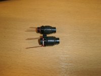
the L1/L2 coil´s on the picture is from my original 606, i have measured them with a agilent 4263b lcr meter.
100hz 1volt= L= 2,48 uh R= 4,85mohm Q= -0,3
1khz 1volt= L=2,24 uh R= 30,2mohm Q= -2,1
10khz 1volt= L=2,07 uh R= 1,28 ohm Q= -9,9
100khz 1volt= L=2,1 uh R= 159 ohm Q= +114,2
wire is 0,54 mm
core is 15,5 mm long and Ø 5,3 mm
and there are 11 vindings.
the other picture is my clone of the 606/909 and i use ferrite cores from pc supplys, they measure 21mm long and are Ø 6mm with 1mm wire and 7 vindings works perfect.
sorry for little glumsy pictures but my camera ain`t better.
Attachments

Interesting that the original coils use such thin wire. My original coils were 0.4mm and they only got warm.
It seems like higher permeability material than Quad used, which I guess you'd expect in PC power supplies. Good that it worked out for you.
almost certainly down to suiting the coil power to the domestic duty of the amplifier.Interesting that the original coils use such thin wire. My original coils were 0.4mm and they only got warm.
Normal domestic duty probably operates with average power outputs of 1W
At those typical output currents the coil heating is nearly nil.
The transients at +10dB do a lot more heating but the duty cycle is so short that warm is about as hot as the coils ever get.
Transients of +20dB have so short a duty cycle, they have virtually no heating effect.
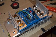
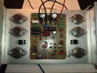
Well the second channel is now under test, with its improvements.
1. It's got the 1.0mm 4.0uH inductor on it.
2. It's got those thinner brown insulators on the BD244s.
It did crackle a bit when I first powered it up but that is probably down to the multitude of temporary connections to it under test.
It seems OK now but it's only running at a fraction of a watt.
1. It's got the 1.0mm 4.0uH inductor on it.
2. It's got those thinner brown insulators on the BD244s.
It did crackle a bit when I first powered it up but that is probably down to the multitude of temporary connections to it under test.
It seems OK now but it's only running at a fraction of a watt.
Attachments
Last edited:
Choices - choices - choices.
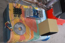
Now I've got to shoehorn this baby into a chassis.
I've got 2 x 800VA 40-0-40V and 2 x 250VA 35-0-35V transformers.
Obviously the 2 x 800VA are better sonically but the 2 x 250VA fit far better.
In order to fit the 2 x 800VA I'm going have to pancake them together, whereas the 2 x 250VA fit nicely mounted vertically.
- Home
- Amplifiers
- Solid State
- QUAD 909 Clone