Thank you for your reply, and sorry for delay as I had a pick-up at airport
I admit have a limited understanding of circuits and try to follow the experts, however there is scant info posted on the expected voltages around the transistors in an ideal state. One seemingly knowledgable enthusiast said that the bias on Tr9 and 10 should not exceed 0.4v, which triggered my query. The diode arrangement is now standard on 405-2 circuits so it must be right.
If you confirm as you have that the voltages are acceptable, then I can be confident in tidying up other areas of the boards.
Oops I got that wrong. The intent is to add to the Vbe of Tr10. It reduces the dead zone where neither Tr9/10 is conducting. Reduces THD by 2/3 on measurement.
OK. I'm probably viewing this from the perspective of biasing on conventional class A and A/B stages, but of course this circuit is not like that.
The Class C dumper stage is under-biased, and your Vbe readings show it. After adding D13 and removing D6 it is still under-biased, but still under-biased, so still Class C.
Mine are the very early boards, when I got the amp most of the current-limiters had been removed/shorted out except the crow-bar clamp which I have replaced (and tested) with new components. As well as ESL63s I have ESL 57s, so I have converted the over-volts link to the later D8/9 position.
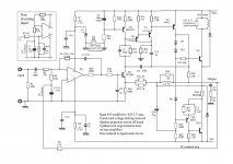
Glad you've got it up and running Sensei..... The error you noted in the schematic in post 1 was corrected in post 8, but I've attached it here again.
In the original Quad 405 Service Manual, there are some diagrams with voltages at various parts of the circuit for testing. I don't have a copy available at the moment, but if you can't find it on Google, I'll put it up here when I get a chance...
In the original Quad 405 Service Manual, there are some diagrams with voltages at various parts of the circuit for testing. I don't have a copy available at the moment, but if you can't find it on Google, I'll put it up here when I get a chance...
Attachments
Thanks, tomorrow (sat) I'll post up the circuit to where I'm at, it's running fine now. I did make an error as I put C4 as 1500pf instead of 150nf, no wonder the bass was heavy!
As mentioned, it's running well with perfect background silence using my ESL 63s, except that senstitivity needs increasing as for normal volume level the control is at 12-1 o'clock (using an Audiolab 8000 as pre-amp). R7-8 are 1W so I will up them to 2W
So, bearing in mind the very early boards, are there any further worthwhile component changes needed (perhaps the IC?).

So, bearing in mind the very early boards, are there any further worthwhile component changes needed (perhaps the IC?).
In fact, Quad 405. there is nothing that needs to be modified.Thanks, but which component is that?
If you must want to change it. You can make 0.68uf larger. For example, use 1 UF
It can reduce the attenuation of low frequency.
All other places. yes. All places. There is no need to change.
Because it doesn't make any sense.
Do not replace the operational amplifier. It's useless.
In addition. Remember never to use MOSFET.
In fact, from my observations.
At present, there is no one's level. It can be compared with the inventor of quad405.
Most people just put Ferrari cars. Changed into Passat
If you do that without changing the servo you will get incorrect bass response. You have to change both in the same ratio. They form a 2nd order HP filter.You can make 0.68uf larger. For example, use 1 UF
It can reduce the attenuation of low frequency.
And Quad changed the opamp: why shouldn't anyone else?
Last edited:
My idea is based on the results of my experiment.If you do that without changing the servo you will get incorrect bass response. You have to change both in the same ratio. They form a 2nd order HP filter.
And Quad changed the opamp: why shouldn't anyone else?
I probably finished the first quad405 in 2006.
During this time. I try all kinds of changes. Different PCBs. Although they are not sold.
But many Chinese customers are using them. Then give me feedback on the results.
There are measurement results. Listen to the sound feedback for a long time.
I don't want to discourage others. But in fact, quad405 has almost no modification.
The effect is worse. Feedback becomes worse. Of course, DIY means that everyone can do what they want.
So. In fact, you don't need to consider others' opinions.
Maybe you will do better than quad.
In addition, I would like to add. In fact, it is Quad company.If you do that without changing the servo you will get incorrect bass response. You have to change both in the same ratio. They form a 2nd order HP filter.
And Quad changed the opamp: why shouldn't anyone else?
The changes they made themselves. It is not necessarily useful.
Because we compared quad405, quad606, and quad707.
We found. Quad405 has the best effect. 606-707 the sound is falling, not rising.
If you are interested, you can compare it. A lot of things. I saw it on the Internet. It's not true.
What you see on the Internet is only what others want you to see. Not the real thing.
😛
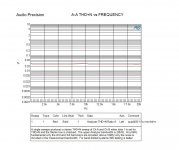
I don't know what 'the sound is falling, not rising' means, or 'feedback becomes worse' either, but 'not necessarily useful' is certainly false. I have both auditioned and measured many examples of each of 405, 405-2, 306, 606, 606-2, 707, and 909, and they are all successively better on objective measurement. The D13 mod in the 405-2 alone reduces distortion by 2/3.
If you want an amplifier with minimal distortion.I don't know what 'the sound is falling, not rising' means, or 'feedback becomes worse' either, but 'not necessarily useful' is certainly false. I have both auditioned and measured many examples of each of 405, 405-2, 306, 606, 606-2, 707, and 909, and they are all successively better on objective measurement. The D13 mod in the 405-2 alone reduces distortion by 2/3.
Lm4702 can be made. about THD 0.0002% And it's cheap.
In fact, I often measure amplifier distortion.
But. in fact. It's useless.
Or use a simple modified version of Douglas circuit.
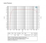
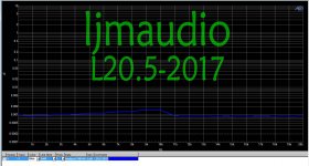
For example, l20.5 distortion is 0.0015%
But in fact. Although quad405 has higher distortion.
But its effect. Better than quad606,707.
Because I made it all. And measure.
I have used more than 2000 quad405, 405-2
We also compared quad606707 and made them.
https://www.diyaudio.com/community/threads/quad707-design-documents.388336/page-2#post-7077674
Attachments
-
 L205-2017.jpg182.5 KB · Views: 116
 -
 QUAD405-thd.jpg94 KB · Views: 124
 -
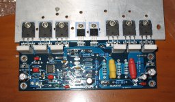 IMG_2977.jpg257.5 KB · Views: 124
 -
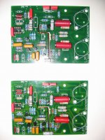 2.jpg449.2 KB · Views: 130
 -
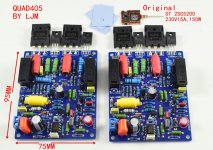
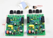 405-2-NJW0281G.JPG314.6 KB · Views: 117
 -
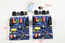 QUAD405-NJW0281-1.JPG311.2 KB · Views: 114
 -
 DSC_0007_副本_副本.JPG104.3 KB · Views: 104
 -
 405-5200-1.JPG372.1 KB · Views: 111
 -
 405TO3-2.jpg312.8 KB · Views: 119
 -
 TB2dqLqeb3nBKNjSZFMXXaUSFXa_!!36508936.jpg417.2 KB · Views: 119
Last edited:
I'm talking. I made 405 405-2 606707.'Its effect is better' how? Despite higher distortion? What exactly are you claiming here?
405 sounds better. Others are not good.
Any 405 change is not good either.
THD of 405 is not low and does not need to be reduced. Thd is useless.
Sorry, my English is not good. Is this description understandable.
We can translate by: "Subjective sound quality does not necessarily mean high technical specifications."
🙂
🙂

- Home
- Amplifiers
- Solid State
- QUAD 405 updates and clones