
Hello!
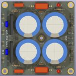
Again a new version of the PSU board.
Version [1.0.3] (30-08-2023)
It shouldn't move now.
Stef.
Again a new version of the PSU board.
Version [1.0.3] (30-08-2023)
- Changed C1 and C2 for 10nF 100V COG (do not use MKP here with Saligny bridge).
- Updated schematic with available Mouser part number and datasheet links.
- Updated PCB for new C1 and C2 footprint (pitch of 5mm).
- Updated BOM.
It shouldn't move now.
Stef.
Attachments
I would like to ask you for the type and brand of resistors that you changed to the Q17-V13 PCB (Tim1999de), I would also like the item numbers and their values (parts list and vendor), or in a PM message. Well thank you ! rado22Tim's attention to detail and endless tweaking has further refined Q17. I've had this amp in my system for the last 10 days and it sounds wonderful. Not going to lie, the board layout seemed a bit busy at first. But after building it all components perfectly fit together like a puzzle. I took some liberty choosing resistor type and brand but followed the BOM recommendations exclusively for the rest of the components. This latest layout has even more tweaks then my freshly built boards. Having the UMS hole spacing is a helpful feature for buying ready machined Modushop chassis and the additional space given around L1 is welcomed.
The Q17-V13 is built in the same chassis with psu as the previous Q17 using Stef's boards. It's been alternating between driving two different speakers, B&W CDM9NT (8R/90dB) and a DIY Tang Band W8-2314 coaxial in a TL enclosure (4R/85dB). The amp is dead silent when idling, delivers deep controlled bass, clear non-congested middle and fatigue free top end. My Keeper Amp's Stable is getting crowded, but will need to make room for this one 😉.
Big thanks to Tibi, Stef and Tim for sharing the Q17 Amplifier and the constant drive to improve upon the original!


rado22,
Just so you know, you also reported the post to which you are replying. This alerts all the Moderators to a concern. No concern was noted in the report. May we presume hitting the wrong button?
Hello everyone,
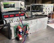
The Q17-Mini 2.0 with the new Q17.3 circuit seems to work well. I tested it quickly from 20Hz to 20KHz at 30Vdc (my 50V test power supply is dismantled for the moment). DC offset is around 1mV (R32 straped). I still have a lot of testing to do but it seems to be a good start.
It works with a JFE150 SMD on the back of the PCB since I no longer have an LSK170B. Good thing because the JFE150 is much cheaper than the LSK170B for identical performance.
Since I received my new generator, I will trying to do the full tests soon.
Have a good day,
Stef.
Attachments
Hello Stef,
do you actually also do optimization of the circuit by listening test with loudspeakers?
It's nice to get good measurement results, but I don't know of any measurement method that is as complex as the human voice, so it does need listening comparisons, or?
How does the new circuit sound relative to the old one?
Regards Tim
Cool Tim. Everything in its time. There, the welds are still warm. 😉
Good evening.
Stef.
EDIT: if you want to know, the Turbo 1.2 passed the Dynaudio tests successfully but the transformer did not support several hours of operation. So, I ordered a custom “audio special” one. One month delay. In the meantime, the Turbo is on a table to taunt me.
Good evening.
Stef.
EDIT: if you want to know, the Turbo 1.2 passed the Dynaudio tests successfully but the transformer did not support several hours of operation. So, I ordered a custom “audio special” one. One month delay. In the meantime, the Turbo is on a table to taunt me.
Last edited:
Ešte sa v tom nevyznám, každý začiatok je ťažký... Ďakujem
rado22,
Aby ste vedeli, nahlásili ste aj príspevok, na ktorý odpovedáte. To upozorní všetkých moderátorov na problém. V správe neboli zaznamenané žiadne obavy. Môžeme predpokladať, že stlačíme nesprávne tlačidlo?
Ešte sa v tom nevyznám, každý začiatok je ťažký... Ďakujem
Can we also please post in English 🙂
I'm not familiar with it yet, every beginning is hard... Thanks
Hello,
I uploaded a preview of the Q17-Mini 2.0 to my Github repository.
The measurements are completed. I didn't find any technical faults at first glance. You will find them in the Github repository. The Q17-Mini 2.0 has technical specifications a little better than the 1.3 but a little worse than the Q17-Turbo 1.2. On the other hand, the curves at the scope are better than the Q17-Mini 1.3 AND the Q17-Turbo 1.2. This is all relative because the measurements are already very good.
I also found no faults during assembly on the 2.0 PCB. I'm waiting a little longer before uploading the Gerber files.
In terms of sound, I compared version 1.3 and 2.0 in mono on my Contrara MK1. The sound is very similar but I found that the sound was a little more slightly "brighter" with the old 1.3 and the Q17-Turbo 1.2. I'll have to try with an LSK170B instead of a JFE150. Maybe that's where it comes from. The differences remain minimal. This is the beauty of the Q17 circuit (like the QUAD405 in fact), it is relatively stable whatever the component brands we use (apart from the power transistors and the opamp).
I will now build a second board to test it in stereo.
Have a nice week-end.
Stef.
Good results 👍 Stef
Can use 2× 2SK209GR JFET ( parallel ) instead Lsk170B /JFE150, If using adaptor board in place?
Can use 2× 2SK209GR JFET ( parallel ) instead Lsk170B /JFE150, If using adaptor board in place?
Don't know. Never tried.
It's a single LSK170B (Q7) OR JFE150 (Q7') transistor but not both at the same time.
Stef.
It's a single LSK170B (Q7) OR JFE150 (Q7') transistor but not both at the same time.
Stef.
Hello,
I uploaded the Q17-Mini 2.0 Gerber files on the Github repository. Enjoy!
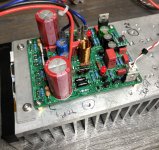
I updated the power supply of my Q7-Mini amp with the PCBs I made. The whole thing seems quieter and more punchy to me with the L75. A plus that was worth the dismantling.
Good end of weekend.
Stef.
I uploaded the Q17-Mini 2.0 Gerber files on the Github repository. Enjoy!
I updated the power supply of my Q7-Mini amp with the PCBs I made. The whole thing seems quieter and more punchy to me with the L75. A plus that was worth the dismantling.
Good end of weekend.
Stef.
Attachments

Hello,
I uploaded the version 1.2.2 of the Q17-Turbo. It's just a small release which adds a J4 jumper to easily shunt R32.
Best regards,
Stef.
I uploaded the version 1.2.2 of the Q17-Turbo. It's just a small release which adds a J4 jumper to easily shunt R32.
Best regards,
Stef.
Attachments
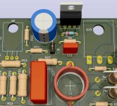
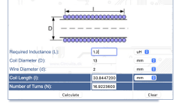
Stef, one question regarding the coil: I have plenty of 2.0mm copper wire left from an earlier project. Can I use this rather than the 1.5mm that you have specified?
Hello,
A bit thick. You will have a beautiful tower 35mm high. 😉
http://www.circuits.dk/calculator_single_layer_aircore.htm
The tool gives an estimate. It would be necessary to check with a device.
You will also need to file the wire. The holes are 1.7mm in diameter.
Good night.
Stef.
A bit thick. You will have a beautiful tower 35mm high. 😉
http://www.circuits.dk/calculator_single_layer_aircore.htm
The tool gives an estimate. It would be necessary to check with a device.
You will also need to file the wire. The holes are 1.7mm in diameter.
Good night.
Stef.
Attachments
I have a 400VA dual 37-0 toroidal and All Cee's PSU.
These are producing +-48VDC.
Is it enough to build this Q17 2 pair output (version 2.8) of @iTiberius?
These are producing +-48VDC.
Is it enough to build this Q17 2 pair output (version 2.8) of @iTiberius?
Hello,
48V is way too low to drive a P2. The minimum is 58V with a target more towards 60/61V. Below 58V, the power MOSFETs do not work optimally.
You should also not use a CRC power supply with an amp like the Q17.
It's strange that your 2 x 37V AC toroid only outputs 48VDC. Normally with 37Vac it should be around 50/51Vdc.
Regards,
Stef.
How that affects Q17 and sound quality?You should also not use a CRC power supply with an amp like the Q17.
- Home
- Amplifiers
- Solid State
- Q17 - an audiophile approach to perfect sound