
@stef1777 looks like the BOM is shared in the same pcbway link.
Thanks. I don't have a PCBWay account to download the file.
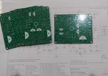
No reference for L1 in the BOM?
Stef.
C1 10mF 16V d16mmWhere is the BOM?
C2 10mF 16V d16mm
C3 0.47 275V
C4 0.47 275V
CR1 S10K275
D1 KBU1005
FS 3.15A
R2 220R 2W
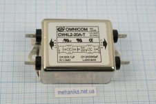
I use L1 filters from faulty computers power units. Such a specificity of work. )
Last edited:
Hi Yurick,
That doesn't speak to me much. Do you have a photo or a reference to catch the specs?
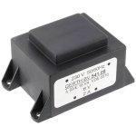
Not easy to find an 1x8V transformer. I found this model which is advertised for 2A.
Gerth PTA540801
56x47x38mm
24€
It should fit in the chassis. Hopefully it will be powerful enough. The 9V 15VA that I use for the moment does not heat up.
I did some tests. The transformer begins to hum around 234V/235V. We can not say that it has very tolerant specs.
Stef.
That doesn't speak to me much. Do you have a photo or a reference to catch the specs?
Not easy to find an 1x8V transformer. I found this model which is advertised for 2A.
Gerth PTA540801
56x47x38mm
24€
It should fit in the chassis. Hopefully it will be powerful enough. The 9V 15VA that I use for the moment does not heat up.
I did some tests. The transformer begins to hum around 234V/235V. We can not say that it has very tolerant specs.
Stef.
Attachments
https://www.aliexpress.com/item/100...order_list.order_list_main.676.30b31802GBhKUWDo you have a photo or a reference to catch the specs?
https://www.aliexpress.com/item/400...order_list.order_list_main.756.30b31802GBhKUW
Thank Yurick,
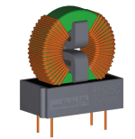
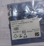
I understand now. You meant common mode choke coil like the one I pictured. This one is a 270uH. I have others lying around on old SMPS. I'll see what I have in stock. You also need the right size. Do you have a preference on the value in uH?
Stef.
I understand now. You meant common mode choke coil like the one I pictured. This one is a 270uH. I have others lying around on old SMPS. I'll see what I have in stock. You also need the right size. Do you have a preference on the value in uH?
Stef.
Attachments
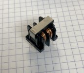
I use this choke with the capacitors with whom it was on the device. I assume that there should be the formulas by which this filter is calculated. I am ashamed to admit, but I never measured inductance.
I looked a bit on Mouser depending on the size of the L1 footprint on the PCB. It seems to be 20 x 10 mm. This reduces the possibilities of model and value. We would rather be in the MH (between 1mH and 4mH) for a maximum current of 4A. The rest is either too large or too small. The one I have put in a picture is twice too small for example. 😉
Stef.
Stef.
Attachments
Regarding the problem of overvoltage, you can connect an inductor in series with the transformer to create an inductive voltage divider. With a series inductor that has a value of 10% of the magnetizing inductance, you will get about a 10% reduction of voltage applied to the primary winding.
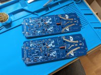
I'm on holiday at the moment and the weather's bad, so I started working on building Tim's Q17.
Yesterday I soldered all the additional boards from his website - rectifier, softstart and speaker protection. Today I continued with the Q17 boards. Although, I started with the most annoying part IMHO: Finding and soldering all the various resistors. Now that that's out of the way, next are the SMDs. Scary, as it's my first time soldering SMDs. I hope everything works out.
Cheers
Lars
Attachments
Hello,
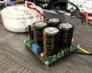
The small compact power supply works well.
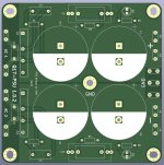
The basic version with just the 4 big capacitors, the two MKP capacitors and the LEDs.
Tomorrow, I'll upload a version 1.0.2 with some cosmetic modifications.
Good evening,
Stéphane
The small compact power supply works well.
The basic version with just the 4 big capacitors, the two MKP capacitors and the LEDs.
Tomorrow, I'll upload a version 1.0.2 with some cosmetic modifications.
Good evening,
Stéphane
Attachments
Hello,
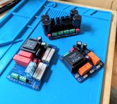
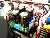
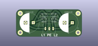
The new "basic" power supply is in place. Approved!
It's nice oval holes for setting up (Thanks Tibi).
I added a GNDPWR T-pad using the new PSU's extra pad and am modifying the wiring right now.
Good afternoon.
Stef.
ps: version PSU 1.0.2 uploaded.
The new "basic" power supply is in place. Approved!
It's nice oval holes for setting up (Thanks Tibi).
I added a GNDPWR T-pad using the new PSU's extra pad and am modifying the wiring right now.
Good afternoon.
Stef.
ps: version PSU 1.0.2 uploaded.
Attachments
Last edited:
Hello Stef,
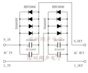
Your schematic contains many components, however the ones shown at my board above are sufficient to achieve electrically the identical effect as in your circuit. I don't need double diodes in parallel, it is also not necessary to use capacitors in parallel. The high frequency filtering of the mains current takes place on the switch-on delay board for me, so this one uploaded here is sufficient. There are two stages, each with two diodes and a capacitor, so that each stage drops about 0.7V voltage.
Tim
- Home
- Amplifiers
- Solid State
- Q17 - an audiophile approach to perfect sound