Hello manniraj,
What did you finally do for your PSU?
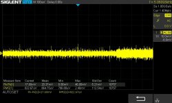
You can use a switching power supply but it's usually much louder than an analog power supply. If you have high sensitivity speakers, I don't recommend you SMPS because you will hear the background noise. If you have low sensitivity speakers as 88dB, it should be ok. For example, a Connex RXE SMPS turns around 60mVRMS, a simple analogic power supply will be 4 to 6 times less noisy.
Stef.
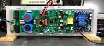
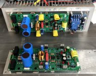
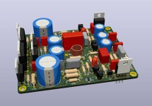
ps: I have a little progress on my amp. I have completed the power/protection block and soft-start. It will be fixed with 5 screws on the bottom of the box.
What did you finally do for your PSU?
You can use a switching power supply but it's usually much louder than an analog power supply. If you have high sensitivity speakers, I don't recommend you SMPS because you will hear the background noise. If you have low sensitivity speakers as 88dB, it should be ok. For example, a Connex RXE SMPS turns around 60mVRMS, a simple analogic power supply will be 4 to 6 times less noisy.
Stef.
ps: I have a little progress on my amp. I have completed the power/protection block and soft-start. It will be fixed with 5 screws on the bottom of the box.
Attachments
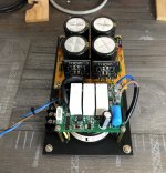

My own Q17-Mini is built with a 2x35v 160VA + 2 x 10 000uF + 1uF per rail. This is quite sufficient for everyday music.
Stef.
Stef.
Hi Stef, may I ask which protection board you're using?I have a little progress on my amp. I have completed the power/protection block and soft-start. It will be fixed with 5 screws on the bottom of the box.
Thanks
Christophe
Hi Christophe,
Here it goes.
DCP-1HC
https://www.ebay.com/itm/174217395697
It is a small company in Israel. It is well made and with many features but the shipping is expensive. Do not take the stereo model, it has a common ground and can create ground loops.
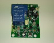
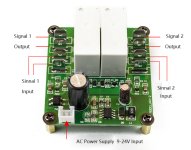
I like this one also in stereo for amps of 100W or less. The Chinese have just restarted production. It was the only floating mass stereo model that I know of. Very small but good relay. It's the same company that makes the softstart that we see in the photo of the power supply that I published a few posts before.
RX-2
https://www.aliexpress.com/item/4000419999179.html
Both models need an external 12VAC small transformer.
Regards,
Stef.
Here it goes.
DCP-1HC
https://www.ebay.com/itm/174217395697
It is a small company in Israel. It is well made and with many features but the shipping is expensive. Do not take the stereo model, it has a common ground and can create ground loops.
I like this one also in stereo for amps of 100W or less. The Chinese have just restarted production. It was the only floating mass stereo model that I know of. Very small but good relay. It's the same company that makes the softstart that we see in the photo of the power supply that I published a few posts before.
RX-2
https://www.aliexpress.com/item/4000419999179.html
Both models need an external 12VAC small transformer.
Regards,
Stef.
Attachments
Last edited:
Thanks Stef!
Yes, the one with the softstart was the one I was interested in. The RX-2 seem not to be available anymore. But the one with the softstart is: KYYSLB PSS-B Audio Amplifier High-power Power Supply Soft Start
Yes, the one with the softstart was the one I was interested in. The RX-2 seem not to be available anymore. But the one with the softstart is: KYYSLB PSS-B Audio Amplifier High-power Power Supply Soft Start
Can use 2SK1530 / 2SJ201 in Q17 mini 1.3.
I have available in stock ,please suggest any changes need in component value if using yes
I have available in stock ,please suggest any changes need in component value if using yes
I have a question for the experienced amp builders?
I am looking for an alternative to the Fairchild FJV1845FM and FJV992FM for a new version of the Q17. Here Tibi built the amplifier in a way that it always needs a high small signal gain. I have now found the following transistors, which have a suitable small signal gain and even the same design and pins: Diodes Incorporate ZXTN25040DFH and ZXTP25040DFH
In other projects I have read and tried myself that there are Zetex transistors that are very low noise, can this be generalized? Are there parameters in the datasheets that allow a conclusion about the component noise behavior? Is anyone here who know these new transistors?
Basically, according to the data sheets, the transistors offer a good power reserve, which I want to use for a high load and high longevity, but not at the expense of a higher noise floor of the amplifier, since it is a quality in itself that the Q17 exceptionally fine and detailed resolution.
Regards Tim
The future is coming!
No idea, sorry.
Can use 2SK1530 / 2SJ201 in Q17 mini 1.3.
I have available in stock ,please suggest any changes need in component value if using yes
No idea, sorry.
I see there are three competing variations of the Q17. Is there a schematic diagram for this one? I'm trying to find out what the extra filters in this version do.Hello all,
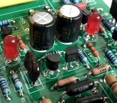
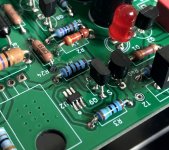
I have implemented some suggestions from the community in my Q17 design and now present this result.
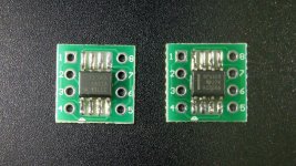
One major aspect was SMD soldering directly to the board to avoid additional sockets. Also, this involved using suitable MosFET and transistors that are available and do not need to be matched. In this regard, Vunce successfully tested the Dual MosFET NDC7003P in my design. This is the smallest of the SMD devices, so footprint optimization was an important detail. On my layout, the SMD components are also turned in such a way that they are easy to solder by hand, even when soldering with a larger tip. This eliminates the following problem points: 1. the small MosFET and the small transistors, which are difficult or impossible to buy 2. the issue of thermal coupling of Q12 (which, according to the current experience of forum members, is more trouble than benefit).
Another aspect is the continuous perfection of the components, here I have the following contribution: Q6 = TK4K1A60F.
This is a Toshiba MosFET with perfect characteristics for the application. It has a low capacitance, is ideally suited for the task in terms of power and has a higher internal resistance. The last characteristic is a very ideal one to dominate the amplifier. In simulation, the Toshiba behaves more favorably, compared to the FQP and much more favorably than the IRF610. In the analysis and also in my test circuits, it turns out that the IRF9610 always works more as desired than the IRF610. The IRF9610 has mostly internal resistances in the range of 2 to 3 ohms, which is very favorable. This results in a pair for Q5 and Q6 of IRF9610 and TK4K1A60F.
The circuit also features the filters I designed (L2, L3, C27, R22, C-GND and R-GND) which provide outstanding silence. This silence results from the fact that due to the filters the input GND is not loaded with noise neither from the power side, nor from the driver stage via R6. This increases the dynamic range of the amplifier.
The circuit also contains the old wiring of Q13 and Q14 with a high series resistor (as presented by Tibi at the beginning of the project) to achieve a high voltage stabilization for the driver stage. This effect is supported by the numerous capacitors on my layout, so that the amplifier can play finest nuances even in this form.
A further facilitation for the construction is the extended layout with a lot of space for the coil, the connection contacts (for usual flat plugs with p = 5mm), as well as a hole pattern in the standard 80 x 40 mm grid size.
Finally, a very practical point:
There is a parts list, with components that Mouser has in stock.
I tested the Q17 in this version single-channel at 500W transformer with a 21 inch 4 ohm subwoofer, there he comes into sweat, with usual speakers, even with large ones, he plays in all volumes sovereign, detailed and controlled.
Have fun with building
Regards Tim
Hello everybody,
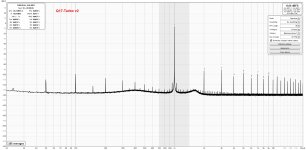
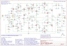
I am pleased to present to you the new version 1.2 of the Q17-Turbo based on the latest developments of the Q17.3 circuit. After several weeks of work with Tibi, the new version is ready and tested.
Q17-TURBO-1.2
Version 1.2 introduces two major changes to the original Q17 schematic. A new Erno Borbely cascode type using JFET & depletion NMOS (Q7, Q8) has been added. Current mirror has been updated to a Wilson CCS with BS250 and NDC7003P (Q9 & U2). This evolution was made possible thanks to the help of Tiberiu Vicol which made it possible to evolve the original scheme towards new performances.
This new version requires at least the soldering of one SMD component to be able to benefit from the use of a high-performance component to drive the Wilson Current Mirror circuit.
Read the CHANGELOG file to know what's new.
Regards,
Stef.
Attachments
I will soon be able to listen to it in stereo. The second board is finished. I'm just always waiting for screws that I miss. My first package was lost. I also bought two OPA828 to compare with the OPA1611.
Stef.
Stef.
Attachments
Stef,
I am happy about the new suggestions.
Therefore immediately a question to it:
The Wilson current mirror you have shown in the schematic is mirror the current across Q12-R24-R25, why? Is this a feedback loop from Q6?
Tim
I am happy about the new suggestions.
Therefore immediately a question to it:
The Wilson current mirror you have shown in the schematic is mirror the current across Q12-R24-R25, why? Is this a feedback loop from Q6?
Tim
Hi Tim,
It's more of a question for Tibi. 😉
In any case, the new optimised CCS is super efficient because you get less than 1mv of DC offset at the output (820uV during my best measurements with a good power supply). Thanks to the NDC7003P.
Stef.
It's more of a question for Tibi. 😉
In any case, the new optimised CCS is super efficient because you get less than 1mv of DC offset at the output (820uV during my best measurements with a good power supply). Thanks to the NDC7003P.
Stef.
Attachments
Sorry, I had to delete some of the files from the Github repository due to a last minute issue. I deleted source files and PCB files. I will reload the files as soon as possible. Do not use them if you have downloaded them.
Stef.
Stef.
Hello folks,
The Q17-Turbo 1.2.1 is published. Gerber's files and KioCAD source are now available.
Enjoy!
Stef.
ps : I am working on the 2.0 version of the Q17-Mini which will implement the latest improvements of the Q17 circuit. It should be available in September.
The Q17-Turbo 1.2.1 is published. Gerber's files and KioCAD source are now available.
Enjoy!
Stef.
ps : I am working on the 2.0 version of the Q17-Mini which will implement the latest improvements of the Q17 circuit. It should be available in September.
Attachments
Question
Can I use 2x38VAC transformer. Or will the voltage be to high for the original Q17. Yes I have the board an component’s with the special rectifier.
Can I use 2x38VAC transformer. Or will the voltage be to high for the original Q17. Yes I have the board an component’s with the special rectifier.
- Home
- Amplifiers
- Solid State
- Q17 - an audiophile approach to perfect sound