Hi Victor !
Q17 with 8 pairs is another fall of mine on the dark side of the audiophile force.
Let's put this way:
- one pair of FQA46N15 & FQA36P15 already move my Triangle speakers as never before
- two pairs have shaken the dust in my sofa
- eight pairs - because I can and such beasts exists. One must rule them all.
Regards,
Tibi

Hello Tibi,
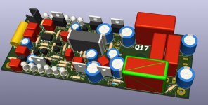
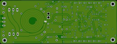
it is really much less work to adjust the layout with the new KiCad. I have compressed it a bit so that the large film capacitors also fit on the PCB. The MosFet now also move to the inside, so it only needs 8 x 16 cm area. It's definitely not easy to assemble, but for a couple - never mind.
I will report when it is finished.
Regards Tim
Attachments

Hello Tibi,
it is really much less work to adjust the layout with the new KiCad. I have compressed it a bit so that the large film capacitors also fit on the PCB. The MosFet now also move to the inside, so it only needs 8 x 16 cm area. It's definitely not easy to assemble, but for a couple - never mind.
I will report when it is finished.
Regards Tim
Looks nice !
Do you use series LED's instead zener on opa regulators ? If yes, than you must choose these to summ ~18V. Over mosfet you will loose 3-4V, so regulator output will be 14-15V.
Regards,
Tibi
Gerber files imported in Sprint Layout are not OK. Output connected to GND ? Electrical test , the same .🙁
As far I understood (from KiCad forum), here is the mother company of gerber Reference Gerber Viewer, by the developer of the Gerber Format
Also, KiCad developers mention that KiCad is one of the few EDA that fully comply with gerber standard. I do not know too much about gerber standards, but I like what KiCad has become, so I trust them for their word.
What I want to highligt is that, if you want to check your gerbers for compliance and errors, Reference Gerber Viewer, by the developer of the Gerber Format is the place to go.
Alex, I'm sure you can design this board far better than me. I see there are people that would like to have a drop-in replacement for original Quad405 boards. Why do not make one ?
Regards,
Tibi
Last edited by a moderator:
I think what alex MM try to say is the output point (+circle via) connect to ground whereas the rectangular via (-) does not connect to anything. I upload to jlc pcb and the result is the same.
Yes, you are right. I'll correct this. Last time I have rotated this connector ...
Thanks !
Regards,
Tibi
Thanks !
Regards,
Tibi
Hello Tibi,
right, I would need 8 LEDs to get to 18V, but only 3 mm size of the available space will do. I will replace this with a combination of low voltage Z-diodes and green LEDs. I have read that Z-diodes of low voltages are supposed to noise less.
About the PCB layout. I'm actually more interested in the resistance of the inductor and when it blows like a fuse. The thickness of the copper layer on a normal PCB is very small, the specification of 0.5 unces per surface is not clear. Possibly it is 35 um in the case of JLCPCB. Then the 2 mm wide inductor should have a conductor cross-section of 0.07 mm² and approx. 50K overtemperature at 4A. I calculate a resistance of 0.21 Ohm from this, provided the copper thickness is correct.
Another point is the ground on the board. I therefore put the ground on both sides - the one from the input and the one from the output - so that the two sides are connected to each other through the contact holes of the components.
The components can be ordered cheaply from Reichelt - except for the QFET - and are half the price of Mouser.
So here's another question: You chose Q7 as the NPN, is the 2N7000 less suitable? I am also surprised that you chose a transistor with hFE in the order of 600, they are supposed to be more noise. So if I interpret what you say, Q7 is a pinhole for the sound. 😉
Regards Tim
Noise
I don't think there is much to gain noisewise, but if you want to lower noise on the OpAmpsupply use 3 x 6V2 zeners
I don't think there is much to gain noisewise, but if you want to lower noise on the OpAmpsupply use 3 x 6V2 zeners
Hello Tim,
Thanks for Reichelt info. Very good prices !
Not sure I understand your question about "You chose Q7 as the NPN, is the 2N7000 less suitable?"
Q7 must be NPN and 2N7000 is a cheap and widely used nmos that will fit here nicely.
I have around 600pcs of 2SC2240GR and 100 2SC2240BL. Both termination GR/BL can be used with excellent performance. Even obsolete now, 2SC2240 is my preferred bjt for low noise. But at this stage the noise is less important. And yes, you pointed right, Q7 and Q5 are very important for final amplifier sound.
Regards,
Tibi

Hello Tibi,
I'm an acoustics engineer, so I don't know much about transistors. I know and have tested myself how important the input transistors of an amplifier are. That's why my self-built old Symasym also have JFET input transistors and no BJT.
So far I have used BJT with medium gain (hFE = 150 to 250). I was surprised that the KSC1845 has such a high gain. This is the reason for my question, also because you write that the control of this transistor is important for distortions, oscillation...
The Fairchild KSC1845s are really cheap BJTs, but that is no argument for their functionality.
I took up the recommendation to use QFETs for Q5 and Q6 and ordered some. rs-parts has the N-chanel, Mouser the P-chanel.
I think my test boards and the components will be delivered in the next few weeks, then I can try out how well the layout can be built and if it can play music 😀
Regards Tim
Ok Tim, I got your question.
In place of Q7 I tried 2N7000 as well, but do not sound good at all. Maybe at higher current will perform better. Also I give it a try to 2SK117 in same position and different drain currents. This will sound good but too smooth for my taste.
Farnell have all QFET's in stoc.
Regards,
Tibi
In place of Q7 I tried 2N7000 as well, but do not sound good at all. Maybe at higher current will perform better. Also I give it a try to 2SK117 in same position and different drain currents. This will sound good but too smooth for my taste.
Farnell have all QFET's in stoc.
Regards,
Tibi
Gentlemen,
Do we have a little high-powered one designed with more number of Output transistors ?
Regards,
Do we have a little high-powered one designed with more number of Output transistors ?
Regards,
Hello,
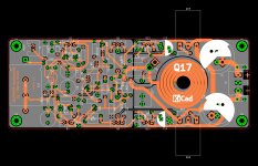
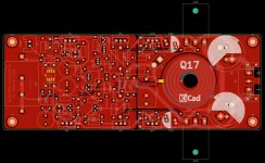
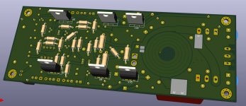
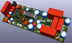
I have further developed the PCB layout, now the resistors are on the back side, also the large transistors are now drawn in upside down.
With this I create space for the assembly of the top side.
Since the QFET are designed for a lot of power, I have added contact areas, so that both the onBoard inductor, as well as a self-wound from thick litz can be installed. Beside the contact points for the connectors and terminals I added solder pads, so you can also solder cables directly.
The 18V diode I have built by a cascade of LED and Z-diode, so everyone can install his personal favorites.
The large MKP should be Wima MKP10 for the power supply, for the 1.0 uF and 0.1 uF capacitor I would install Audyn QS6, which is cheap and very good. Tin foil capacitors would then be for me the extremism variant, for especially clean reproduction. The electrolytic capacitors are Panasonic EB-A, these should have particularly good ribble damping.
Attachments
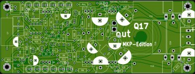
Output connector issue was corrected and I have rearranged component description for all parts. Everything must me more clean and easy for someone who want to make this amplifier with my gerbers.
I can not edit attachments in first post, therefore here it is.
Regards,
Tibi
I can not edit attachments in first post, therefore here it is.
Regards,
Tibi
Attachments
Last edited by a moderator:
- Home
- Amplifiers
- Solid State
- Q17 - an audiophile approach to perfect sound