Do you have a Mundorf model number, or model range (that matches their website) and a voltage rating?
Do you have a Mundorf model number, or model range (that matches their website) and a voltage rating?
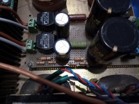
MLytic AG 10.000uF 63V
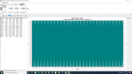
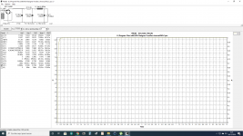
Attached new psudII simulation with corrected values.
Attachments
Last edited:
Specs
Attachments
Last edited:
There is a thread on diyaudo that measures regulation of a 15+15V 30VA R-core - I'd suggest you change the transformer winding resistance to about 5 ohm.
If you modify the load to a step load (eg. change from 280mA to 100mA, or vice-versa, from at 10 secs), and change the reporting to 9 sec delay and show 3 secs, then you will see no 'oscillations' - ie. the CLC filter is over-damped.
If you modify the load to a step load (eg. change from 280mA to 100mA, or vice-versa, from at 10 secs), and change the reporting to 9 sec delay and show 3 secs, then you will see no 'oscillations' - ie. the CLC filter is over-damped.
Given your likely load, and the filtering, you could have used any diode as the rectified current is so low and the winding resistance is so high.
There is a thread on diyaudo that measures regulation of a 15+15V 30VA R-core - I'd suggest you change the transformer winding resistance to about 5 ohm.
Why? Do you refer to source resistance? The source resistance is low 135 miliohms. Do you want to say that I add a 5 ohm resistor between the power transformer & rectifiers?
Last edited:
Given your likely load, and the filtering, you could have used any diode as the rectified current is so low and the winding resistance is so high.
Primary or secondary?
Last edited:
PSUD2, like vintage valve rectifier datasheets, uses an equation to calculate the effective secondary winding resistance. PSUD2 includes a calculator where the primary winding voltage and resistance, and the secondary winding voltage and resistance, can be inserted, and effective secondary resistance calculated (click on the "..." button on the right side of the transformer part value input pop-up window).
The diyaudio thread is linked here: Selectronic Rcore transformer
It shows about 7 ohm of series resistance for the 15+15 windings. On review, your 9+9 windings are in parallel, so I'd suggest using 5//5 = 2.5 ohm. The present value showing in your sim circuit is 0.135 ohm.
The diyaudio thread is linked here: Selectronic Rcore transformer
It shows about 7 ohm of series resistance for the 15+15 windings. On review, your 9+9 windings are in parallel, so I'd suggest using 5//5 = 2.5 ohm. The present value showing in your sim circuit is 0.135 ohm.
Last edited:
How inaccurate are the results, when you measure primary resistance using a variable DC power supply (with current limiting!), a DC ammeter, a DC voltmeter, and Ohm's Law? Wrong by 5%? Wrong by 35%? Is it any better or any worse if you try the same setup to measure secondary resistance?
And for the benefit of the thread starter on "Selectronic Rcore transformer", linked above, here is one possible way to avoid the error
And for the benefit of the thread starter on "Selectronic Rcore transformer", linked above, here is one possible way to avoid the error
PSUD2, like vintage valve rectifier datasheets, uses an equation to calculate the effective secondary winding resistance. PSUD2 includes a calculator where the primary winding voltage and resistance, and the secondary winding voltage and resistance, can be inserted, and effective secondary resistance calculated (click on the "..." button on the right side of the transformer part value input pop-up window).
The diyaudio thread is linked here: Selectronic Rcore transformer
It shows about 7 ohm of series resistance for the 15+15 windings. On review, your 9+9 windings are in parallel, so I'd suggest using 5//5 = 2.5 ohm. The present value showing in your sim circuit is 0.135 ohm.
9+9 windings in series = 10 ohm?
How inaccurate are the results, when you measure primary resistance using a variable DC power supply (with current limiting!), a DC ammeter, a DC voltmeter, and Ohm's Law? Wrong by 5%? Wrong by 35%? Is it any better or any worse if you try the same setup to measure secondary resistance?
And for the benefit of the thread starter on "Selectronic Rcore transformer", linked above, here is one possible way to avoid the error
Thanks Mark, asked the manufacturer so I'm sure is well connected.
The Monte Carlo approach is good for testing all possibilities of component values within their tolerance ranges in a circuit to be sure the circuit works no matter the tolerance combination of the components happens to be in any example.
9+9 windings in series = 10 ohm?
The 15+15V 30VA windings in series appear to be about 7 ohm (post #24 indicates 7Vrms droop for 1Arms loading).
9+9V 30VA windings would be fewer turns, with a higher current rating, so likely to be lower resistance than 7 ohm. Assuming 5 ohm as a series resistance (or even less), then doing some mental arithmetic without the alcohol, the two 9V windings in parallel would be 2.5//2.5 = 1.25 ohm.
- Home
- Amplifiers
- Power Supplies
- Q factor RLC PSU