Do you mean posts #33 and #38 descriptions of estimating the effective secondary winding resistance ? Have you been able to measure the windings resistances with a meter?
Something here does not look quite right: the simulation above is one supply-rail only, but the choke - IF I understand correctly - is a common-mode choke of 2mH?
In which case the series inductance that will appear in the single-rail simulation is the leakage differential inductance of the CM choke: and that is typically about 1% of the CM value - for reputable parts as named already.
So the L value should be around 20uH, not 2mH, for single-rail simulation. Also note that +/- 50, even 100% of that 20uH will have a small/trivial effect in the audio band - that is what I meant by 'close-enough'.
And yes - PSUD will probably not like to report on such small L values*
However - at just 20uH, you can hand-calculate the impedance at 5-10 frequency spots, and simply add those to the R value, to plot your own supply impedance curve - in the time it takes to make a good coffee. Close enough.
* That is in no way a criticism of the immense service Duncan has done in providing PSUD as such an easy -to-use, FREE, modeller for the rest of us!! It is just an artifact of how such things have to work.
Last edited:
I wonder whether it might be possible to experimentally measure the differential mode inductance using a simplistic lab setup?
Perhaps something like a function generator set to output 26.67 Hertz square waves, and a 470 ohm resistor, and the inductor-under-test, and a capacitor whose value is known within ten percent.
The function generator and 470 ohm resistor emulate a step-function current source, which stimulates the LC resonant circuit consisting of the inductor-under-test and the known capacitor.
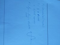
Voila, measure the frequency of the resonance (sinusoidal ringing) and then use the good old equation
Mind you, I haven't tried this myself so I don't know whether it is or is not useful in practice. But it could be worth a try!
(Why 26.67 Hertz? No reason at all. Just keeping you on your toes)
Perhaps something like a function generator set to output 26.67 Hertz square waves, and a 470 ohm resistor, and the inductor-under-test, and a capacitor whose value is known within ten percent.
The function generator and 470 ohm resistor emulate a step-function current source, which stimulates the LC resonant circuit consisting of the inductor-under-test and the known capacitor.
Voila, measure the frequency of the resonance (sinusoidal ringing) and then use the good old equation
- 2 * pi * fresonant = 1 / SQRT(Lunknown * Cknown)
Mind you, I haven't tried this myself so I don't know whether it is or is not useful in practice. But it could be worth a try!
(Why 26.67 Hertz? No reason at all. Just keeping you on your toes)
..nice..
I like 😉
(I am also dim enough to have run curiosity-measurement on a variety of CM chokes single-ended via simple LCR bridge and that's why I suggest - in the absence of better info - start by assuming c. 1% of CM nominal value.
But it may be a much wider-open window.)
I like 😉
(I am also dim enough to have run curiosity-measurement on a variety of CM chokes single-ended via simple LCR bridge and that's why I suggest - in the absence of better info - start by assuming c. 1% of CM nominal value.
But it may be a much wider-open window.)
Last edited:
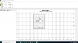
I was going to let the OP prepare a working PSUD2 sim and then hopefully appreciate that any CM choke of that type has no benefit for ripple attenuation, and also likely no noise benefit due to stray chassis coupling. Ie. its the learning curve that is important imho.
Does this refer to the Selectronic R-Core 2x9VAC 30VA from post #20 ? If so then please recheck measurements (note that some multimeters have a hard time measuring resistance for high inductance windings).Yes, 195 ohms primary & 0,3 ohms secondary.
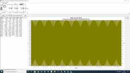
Measured with the oscilloscope the resonant frequency @ 66.66Hz, also measured the PSU AC ripple that's before the Salas regulators 2mV.
Last edited:

- Home
- Amplifiers
- Power Supplies
- Q factor RLC PSU