I've been given 2 humming dual 300B SE amps to fix. They are 2 of 4 identical units from a 2-way system.
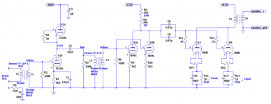
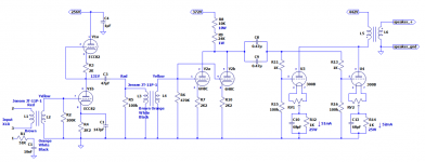
I've attached my reverse-engineered schematic. The first stage appears to be a SRPP amplifier.
That's OK. But why the need for an inter-stage transformer? Why can't the blocking capacitor following the input stage feed directly to the grids of the parallel 6H8C/6SL7GT triodes?
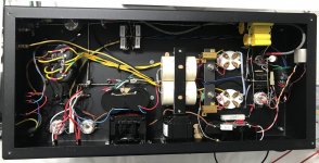
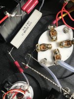
You can see from the picture of the inside of the chassis, that the builder appears to have used an earth follows signal earth bus. Could be multi-stranded silver wire. It's just floating, or hanging when the chassis is the right way up. Very odd. Those I've seen before are a large solid core wire hard mounted on insulators. A lot of the solder joints on the earth bus look dodgy so I'll start there.
I've attached my reverse-engineered schematic. The first stage appears to be a SRPP amplifier.
That's OK. But why the need for an inter-stage transformer? Why can't the blocking capacitor following the input stage feed directly to the grids of the parallel 6H8C/6SL7GT triodes?
You can see from the picture of the inside of the chassis, that the builder appears to have used an earth follows signal earth bus. Could be multi-stranded silver wire. It's just floating, or hanging when the chassis is the right way up. Very odd. Those I've seen before are a large solid core wire hard mounted on insulators. A lot of the solder joints on the earth bus look dodgy so I'll start there.
Attachments
Hi,
At first sight what you draw is not an srpp but looks more like a mu follower ( maybe it is an error in the sketch because 2,2K resistor is coherent with an srpp but it is not located where it should be EDIT: maybe not after all. I'm used to see same value for cathode and 'in between' plate cathode resistor on srpp. So the resistance should be 2,2k on both. Mu followers have more parts used... so i don't know what kind of circuit it is. ) .
No reason for the second jt11p but maybe designer wanted to have it's pre stage galvanically isolated? Maybe he had an humming since start of built and though an interstage could solve this? Or he liked the sound of jt11p ( which doesn't really have a sound ime)?
Last edited:
I think it is an SRPP; the Rk networks are different; there's none at the top, but the one at the bottom is decoupled, so they still fulfill the requirement that they are equal (for AC).
What is the transformation ratio for the transformer? Also, don't discount the possibility that there is no direct logical reason for the xformer ...
Jan
What is the transformation ratio for the transformer? Also, don't discount the possibility that there is no direct logical reason for the xformer ...
Jan
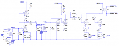
Thanks. Took another look with a magnifier and bright light. I did have the 2K resistor in the wrong place. Definitely SRPP. A mu follower has a capacitor linking the anode of the lower stage to the grid of the upper stage. I'm definitely seeing a hard link there; no capacitor.
Attachments
Yes we agree, an srpp.
Anyway there was some money invested in this build, Jensen, Mundorf and Vcap. It is worth trying to fix them.
I agree having a floating ground is not ideal. Otherwise this doesn't look that bad. Maybe a first attempt ( or one of an inexperienced diyer effort)?
I hope the hum is not magnetical coupling because it might be difficult to fix without relocating to a new box.
Jan i will try this arrangement to see if it have any interesting properties. I liked the srpp i used until now, an other variation is always welcome to try.
Jt11p is 1:1. It is often used as an input for (pro) line level.
The guy who had them built for him certainly agrees with that. So so I. They worked fine for some years so I doubt whether it's a magnetic coupling issue. Sure hums on my bench.It is worth trying to fix them.

I will follow with interest, i'm not so good at fixing this kind of issues ( i'm not patient enough).
I must confess i already used transformers in place of other perfectly valid solution ( and cheaper!) Just because i like what they bring. So i'm with Jan on it.
Once fixed you could try without them ( interstage) and see if it change rendering ( i think it will because there is no termination on secondary on any of the two used and it'll bring ringing in very high freq, so could 'add' something to the recipe). From there install a switch and offer another choice for owner to customise it's sound.
The component i don't see why have been used is the discharge/bleeder resistor (R5: 100k) before the second transfo. Maybe it 'stabilise' impedance on the transformer. More probably to avoid a plop a start up or shuting off of amp by bleeding c3.
Last edited:
Agree; the top Rk must be decoupled because the bottom one is. C3 is the output coupling so you probably want to add another C.
Jan
Jan
Sorry. Missed the 300B grid leak resistors!And the two 300B are missing there grid leak resistors.
Attachments
It definitely is an srpp.
http://www.valvewizard.co.uk/SRPP_Blencowe.pdf
I think r9 is 10w too. 😉
EDIT: ok, Ketje is right it's an 'half mu' or an active loaded grounded cathode. A srpp variant ( it's on last page of Blencowe's paper). I've already used it without knowing it's name... didn't spoted any real difference in my circuit ( but it drive a hiz maybe it could be different with other load).
You could either discard the cathode bypass capacitor or use a second one on the top cathode, as Jan suggested. Or even move the out of the circuit to up cathode and have an 'official' srpp... sounds like you could have fun once hum fixed!
Last edited:
I think r9 is 10w too. 😉
EDIT: ok, Ketje is right it's an 'half mu' or an active loaded grounded cathode. A srpp variant ( it's on last page of Blencowe's paper). I've already used it without knowing it's name... didn't spoted any real difference in my circuit ( but it drive a hiz maybe it could be different with other load).
You could either discard the cathode bypass capacitor or use a second one on the top cathode. Or even moce the out of the circuit to up cathode and have an 'official' srpp... sounds like you could have fun once hum fixed!
If you decouple the top cathode resistor the circuit is still a grounded cathode stage with the Ri of the upper pasive triode as anode resistor.Agree; the top Rk must be decoupled because the bottom one is. C3 is the output coupling so you probably want to add another C.
Jan
The crux of an srpp is that the output current change the grid voltage of the upper triode making that triode an active element in the circuit. Therefore the output has to be taken from the upper cathode, not the anode of the lower triode.
Mona
front end is identical with the "Aikido" input stage, except for C1. To get the top and bottom tube non-linearities to cancel, leaving linear mu/2 gain, the calculations require no C1. So we have two non-linear 12AU7 sections in a linearising circuit, that is unbalanced again, to be non-linear. Maybe by some miracle it is cancelling 2nd Hamonic distortion of the 300Bs. Or maybe they just needed a little more gain.This 'half mu' or an active loaded grounded cathode.
Anyway, for hum, the 1st thing to try would be changing the front end V1 and V2. Maybe some heater to cathode leakage in one of them.
Aikido from Broskie's site:
Last edited:
Yes, agreed. Through both Rk's the same current flows, as well as through both tubes, so they have both the same Vgk. If we then take identical triodes (like in a double triode),we get gain A = 0.5*mu. The absolute value for Vgk doesn't matter (within limits of course), but the should be the same. So if you decouple one, you also should decouple the other.If you decouple the top cathode resistor the circuit is still a grounded cathode stage with the Ri of the upper pasive triode as anode resistor.
The crux of an srpp is that the output current change the grid voltage of the upper triode making that triode an active element in the circuit. Therefore the output has to be taken from the upper cathode, not the anode of the lower triode.
Mona
Unlike decoupling of one of the Rk is the most frequent error.
Jan
Decoupling one or the other (or both) is no error, depends what you want.
If the upper cathode resistor is decoupled that makes srpp impossible.
Not decoupled gives a greater Ri as anode resistor for the lower triode.
The two resistors decoupled giver A=½µ as does without any decoupling.
But decoupling only the lower cathode resistor gives an A greater then ½µ.
Your choice
Mona
If you have non-equal Rks, the gain doesn't reduce to A=0.5*mu, although it still 'works' sort of. There will be a factor Rk1/Rk2 in the gain expression.Decoupling one or the other (or both) is no error, depends what you want.
If the upper cathode resistor is decoupled that makes srpp impossible.
Not decoupled gives a greater Ri as anode resistor for the lower triode.
The two resistors decoupled giver A=½µ as does without any decoupling.
But decoupling only the lower cathode resistor gives an A greater then ½µ.
Your choice
Mona
The nice gain depending only on mu with equal Rks is for me the only thing that it has going for it. Don't take that away ;-)
But as you say, whatever floats your boat!
Jan
- Home
- Amplifiers
- Tubes / Valves
- Puzzling SRPP input stage on 300B SE amp