rongon,
For your post #38.
The graph you re-posted does not have any load lines on it.
It only has the plate curves.
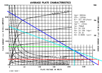
At the far left of the graph, the plate is a very low impedance, it is like a 125 Ohm resistor.
And for plate voltages of from about +10V to +40V higher than the cathode volts.
And at a screen voltage of 300V.
Having the plate swing from +10V to +40V is not going to make a very good amplifier (in my opinion).
Next, we have the Knee of the plate curves, a transition between 125 Ohms to 5500 Ohms.
That is very non-linear.
Then we have the portion of the curves that has plate impedance of about 5500 Ohms.
Beyond that, at even higher plate voltage, the slope of the plate line is even flatter, indicating a plate impedance of perhaps 10000 Ohms or more.
You have to draw Load Lines on the graph in order to see what plate voltage is versus the control grid, g1 voltage.
For your post #38.
The graph you re-posted does not have any load lines on it.
It only has the plate curves.
At the far left of the graph, the plate is a very low impedance, it is like a 125 Ohm resistor.
And for plate voltages of from about +10V to +40V higher than the cathode volts.
And at a screen voltage of 300V.
Having the plate swing from +10V to +40V is not going to make a very good amplifier (in my opinion).
Next, we have the Knee of the plate curves, a transition between 125 Ohms to 5500 Ohms.
That is very non-linear.
Then we have the portion of the curves that has plate impedance of about 5500 Ohms.
Beyond that, at even higher plate voltage, the slope of the plate line is even flatter, indicating a plate impedance of perhaps 10000 Ohms or more.
You have to draw Load Lines on the graph in order to see what plate voltage is versus the control grid, g1 voltage.


OK, thanks for your replies.
Was PRR saying that there are many load lines along which operating points may be chosen, and that the power output would be different depending on those? That I would understand, but then I don't know what the significance of that would be. Any idea what PRR was getting at? He didn't reply after that...
- Yes, I see that they are not load lines.
- I do understand how to draw load lines and what their significance is.
- I don't understand PRR's point in post #25:
A pentode is a 2-slope device. The usual plate resistance is the horizontal part, very high impedance. Just as important for Power is the vertical part, a few hundred ohms. Ignoring limits, you can run almost anywhere between these two slopes; getting different powers.
Was PRR saying that there are many load lines along which operating points may be chosen, and that the power output would be different depending on those? That I would understand, but then I don't know what the significance of that would be. Any idea what PRR was getting at? He didn't reply after that...
Draw a load line = X Ohms impedance from high plate voltage all the way to zero volts on the plate.
Now, choose different sets of plate voltage range along different portions of that load line.
Examples:
Pica a load line impedance that can have a range of plate voltages from . . .
Plate voltage from 50V to 350V
Plate voltage from 100V to 400V
Plate voltage range from 250V to 550V
The ranges are all 300V peak to peak, but the distortion of those examples is far different from one to the other, even though the power output will be the same.
Now, draw on the load line a range of 450V peak to peak, from 50V to 500V.
There will be about 3.5dB more power output than the 300V peak to peak examples (a little more than double of the lower power).
That is all for one load line impedance.
Now, pick another load line impedance, draw in that new load line, and repeat the ranges above (if the load line impedance can fit some or all of those plate voltage ranges).
The load lines, and plate voltage ranges are more restricted for single ended outputs, versus push pull outputs.
For example, single ended is Class A, the output tube is never allowed to go into cutoff (no longer Class A, and sounds terrible).
But for a push pull amplifier, Class AB, the output tubes can go into cutoff (one tube, then the other tube, not both together).
Last edited:
Draw a load line = X Ohms impedance from high plate voltage all the way to zero volts on the plate.
Now, choose different sets of plate voltage range along different portions of that load line.
Yes, that is how one draws a load line, from which one can calculate the quiescent plate-cathode voltage, grid bias voltage, plate current, likely power output, voltage swing, THD. Yes, that is well known.
What was PRR trying to explain with the non-zero-volt vertical line labeled "125 ohms"? Does that show the 'contact potential' point at which grid current is drawn and the pentode now requires a power stage in front of it for its drive signal?
Load line for B+ = 500V, Rload = 2k ohms, Vp = 300V, Vg = -20V, Ip = 130mA
Last edited:
You will find many different control grid, g1 voltages on those plate current lines. Many of them are very far away from the cathode voltage.
Many are not even close to the contact potential and not close to the cathode voltage.
What is happening at those low plate voltages of the plate curves, is the interaction of the plate and screen voltage, the currents that each draws there, and the 'saturation' of the plate, if you want to call it that.
Look at those very large screen currents, it is 'robbing' electrons (current) that would normally be going to the plate.
For a non-gassy pentode/beam power tube, which is operated within the total dissipation limits of the tube . . .
There should be very little or no grid current, as long as the grid is not Either at the Contact Potential voltage, Or the grid is at the same voltage as the cathode voltage.
An over heated tube can do very strange things.
That is one reason there are maximum dissipation limits for the Plate, Screen, . . . and sometimes the limit of the total of those two is Less than the simple sum of those two dissipation limits.
Also, the maximum filament voltage is rated, that limits the heat from the filament (or filament and cathode).
Sometimes the maximum ambient temperature around the tube is rated, and/or convection cooling details like spacing are given, or fan cooling is recommended/required.
Violate any, a couple, or a few of the tubes ratings . . . and get whatever you get.
I think of the region of the plate curves that is 125 Ohms as an area where the 'control grid, g1' no longer has any useable control of the plate current.
Seems like an area you want to stay out of for a single ended amplifier (could cause 2nd harmonic distortion, and if you also operate near the cutoff region as well, a cause of 3rd harmonic distortion of a single ended amplifier.
It also seems like an area you want to stay out of for a push pull amplifier (could cause 3rd harmonic distortion).
Just applying a moderate amount of negative feedback is not going to fix either of these distortions.
Any time that the control grid, g1 is no longer controlling the plate current causes distortion.
Do not use the portions of the load line at the ends of the line, or you get unusual amounts of distortion (plate saturation for push pull or single ended; or plate cutoff for single ended).
Just my opinions and experience.
Last edited:
I don't see the relevance to the question,
What was PRR trying to explain with the non-zero-volt vertical line labeled "125 ohms"?
Last edited:
UPDATE -- 2nd reading, I think I see.
When the Vg2 voltage is far higher than Vp, Vg2 acts like the 'plate', drawing most of the cathode current. In a tetrode this is the region where the kink appears. I guess in a pentode this is where it has a very low plate resistance, draws a lot of current at low plate voltage. Not a useful region for normal circuits.
I still don't see the significance. I would not bias a pentode way down there. Nor would anyone else.
The plate curve graph looks like it comes from a big honkin' horizontal deflection beam pentode. High plate volts, low screen volts, high plate+screen current, high dissipation, with low grid bias voltage. Must have beastly high max plate dissipation. Any idea which tube that is?
rongon,
Good!
You remembered the Tetrode tubes.
A lot of people do not even know they existed.
As usual, I added edits to my Post # 46, . . . After you posted # 47.
I think that history will show that this was a very well known characteristic of very early pentode and beam power tubes.
Those old tube engineers were smarter than most people give them credit.
6L6 beam power metal tube, 1936
TVs were not even a dream in most engineers eyes back then, no need to call it a Deflection Tube when it first came out.
807 beam power tube (you can search for the earliest year of the 807).
Early pentode tubes (I am not going to search for early pentodes, the engineers of pentodes knew what they were doing back then).
The effects of all those old, and all those new tubes, including the KT series tubes is actually very similar.
Radio Amateurs used the 6L6 and G, GA, and GB to build low power output transmitters in the 2MHz to 30MHz bands (Mega Cycles [per second]).
The metal 6L6 had an intrinsic shield that could be grounded.
And, none of the 6L6 family had the useful, but very dangerous plate cap of the 807. High voltage at RF frequencies does not need actual contact for you to get a shock or RF burn.
Last edited:
I dunno what PRR meant, but the "125 Ohm" line has no effect in normal amp operation before clipping.
It only determines the (minimum) plate voltage and thus affects the available voltage swing when the loadline hits the Vgk =0 plate curve.
It only determines the (minimum) plate voltage and thus affects the available voltage swing when the loadline hits the Vgk =0 plate curve.
Last edited:
Rikaro,
The 125 Ohm plate impedance, rp is available at control grid voltages of:
0 volts, -5 volts, -10 volts, -15 volts, -20 volts, -25 volts, -30volts, -35 volts, and -40 volts.
Look at those plate / control grid voltage curves . . . again.
Is your tube already clipping when the grid voltage is at -5V, -10V, -15V, etc.
If so, it is either a very low power tube, or it needs to be re-designed.
Most often, I trust what PRR says . . . even if I do not always understand what he says.
Just my opinions.
I agree, i also don't see any use for that line. But subscribed now to learn if there is any.I dunno what PRR meant, but the "125 Ohm" line has no effect in normal amp operation before clipping.
It only determines the (minimum) plate voltage and thus affects the available voltage swing when the loadline hits the Vgk =0 plate curve.
Sometimes lines are there to tell you where NOT TO GO.
Tubes/Valves is about audio hi fi / stereo tube amplifiers.
It is not about Vacuum Tube Switcher Power Supplies.
Just my opinions.
Tubes/Valves is about audio hi fi / stereo tube amplifiers.
It is not about Vacuum Tube Switcher Power Supplies.
Just my opinions.
@6A3sUMMER :
Not getting your point, please elaborate.
How would the initial slope influence performance before the loadline hits this part?
Not getting your point, please elaborate.
How would the initial slope influence performance before the loadline hits this part?
The "125 ohm" line is known as the diode line, and represents the voltage drop for a particular current if the valve was connected as a diode. If you just look at the Vg=0 curve, and draw a series of loadlines with different loads, you will see that the maximum voltage swing (without grid current) is limited either by this diode line for high resistance loads (flatter load lines) or by the much flatter "5500 ohm line" for lower resistance loads (steeper load lines). The maximum power is achieved when the load line hits the knee of the curve. With higher resistance loads, the power becomes limited by the available voltage swing, and with lower resistance loads the power becomes limited by the available current swing. Given the peaks that are seen in loudspeaker impedance plots, it is usually preferable to have a slightly steeper load line that hits the Vg=0 line to the right of the knee. It is well explained here:
https://atrad-audio.co.nz/turneraudio/www.turneraudio.com.au/loadmatch-4C-PP-tetrodes-pentodes.html
Edit - the comment above saying its preferable to have a slightly steeper loadline only refers to achieving maximum power. In the link, Turner discusses the pros and cons of various loadlines, and recommends flatter loadlines for best performance at normal listening levels.
Last edited:
there are three areas in the power tube plate curves, on the left side where g=0 volts or positive, is the saturation region, where the plate resistance is indeed very very low, 125 ohms is not surprising and will be lower for the bigger tubes, so that the only thing limiting plate current is the external plate or cathode resistors. than on the right hand side is the cutoff region where grid is highly negative wrt cathodes, but tubes are really hard to turn off...
so in between saturation and cutoff, there is an active area which is very big wherein you can operate your tube at...
here the max Pd is the guideline, you can touch that locus of Pd, but you can not stay above the Pd locus or risk your pate turning red, or red plating...
another important spec is maximum cathode current, do not exceed this current of you want your tubes to last,
this of course is at idle conditons where the tube cathodes are asked to deliver currents all the time...
Attachments
Last edited:
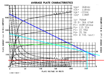
the slope of the loadline you drew is 2k,that is for a common cathode circuit, your B+ is 560v. you Vp is 300, and Ip is 130ma, therefore your plate load must be (560-300)/130ma, or 2K, 34watts....Yes, that is how one draws a load line, from which one can calculate the quiescent plate-cathode voltage, grid bias voltage, plate current, likely power output, voltage swing, THD. Yes, that is well known.
What was PRR trying to explain with the non-zero-volt vertical line labeled "125 ohms"? Does that show the 'contact potential' point at which grid current is drawn and the pentode now requires a power stage in front of it for its drive signal?
Load line for B+ = 500V, Rload = 2k ohms, Vp = 300V, Vg = -20V, Ip = 130mA
View attachment 1214629
now if you are thinking push pull, this will not do...
please look at the loadlines drawn by Miles Prower and see how it is done...
in a pushpull amp, we are looking for OPT's with low dcr's for negligible losses as much as practical...
Last edited:
I was not drawing a good or recommended load line, it was just an example load line. I gave no thought whatsoever to how it would work in real life.
Patrick Turner explained it all quite clearly.
https://atrad-audio.co.nz/turneraudio/www.turneraudio.com.au/loadmatch-4C-PP-tetrodes-pentodes.html
Thank you to tikiroo for providing that explanation and the link to the page from the archived Turner Audio website.
Patrick Turner explained it all quite clearly.
https://atrad-audio.co.nz/turneraudio/www.turneraudio.com.au/loadmatch-4C-PP-tetrodes-pentodes.html
Thank you to tikiroo for providing that explanation and the link to the page from the archived Turner Audio website.
I think most folk would be better served by thinking in terms of the composite characteristics for a push-pull amplifier. RDH4 has a good derivation in Fig. 13.32 on page 574, and several worked examples. Several drawings above have non-sensical lines drawn onto them and seem confused about idling conditions. Remember that a loadline must pass through the idling point (at small signal).
All good fortune,
Chris
All good fortune,
Chris
- Home
- Amplifiers
- Tubes / Valves
- Push-Pull transformer question