I assume you are talking about the spiraly thing?
"ok today i will try this.
i paralleling the primaries the inner most of each primary will be connected together and the outer most of each will be connected together."
Yes.
"the phasing for the pri to sec is not important?"
The bridge rectifier won't care, both AC inputs are the same. Or are you refering to something else?
"i think i will use 8 mil for each pri and 16 mil for the sec."
You should use 16mils for both if you are talking about my suggestion. Using 8 mil primary foil will double the losses in the primary. There will be only half a turn per portion if wound like this so proximity effect is not a problem. Current will flow in the right direction on both surfaces of the wire.
An alternative could be using 8 mil foil wound like sss-pp-ss but the losses will be about 3-4 times higher than the s-p-s-p-s-p-s-p-s winding with 16 mil foil due to both higher DC resistance and proximity effect loss. This might still be an acceptable loss though depending on how much forced air cooling you have.
"as a side note the leakage inductance could be measured by shorting the secondary and measuring the pri inductance?"
Yup.
"i know about vacuum tube switching supplies in research, radar and satelite power supplies, megawatt low freq switching.. this is way different and not all of the principles seem to ttransfer..............."
Cool 😎 I guess the lower freqency (greater skin depth) and higher voltages (thinner wire for the same power) might be one of the things that makes proximity effect less of a problem in these cases.
ok 16 mil for everything
i'm interested in looking into the reasonings you gave me for the way i first did it to follow why it wouldn't work. with currents going different directions on opposite sides of the same winding........
thanks
i'm interested in looking into the reasonings you gave me for the way i first did it to follow why it wouldn't work. with currents going different directions on opposite sides of the same winding........
thanks
Here is an online seminar (free) that's very good and explains it pretty well:
http://training.ti.com/courses/coursedescription.asp?iCSID=1152
On proximity and skin effect loss (this is part of the online seminar too if I remember correctly):
http://focus.ti.com/lit/ml/slup197/slup197.pdf
More:
http://focus.ti.com/docs/training/c...l?sku=SEM401014
http://training.ti.com/courses/coursedescription.asp?iCSID=1152
On proximity and skin effect loss (this is part of the online seminar too if I remember correctly):
http://focus.ti.com/lit/ml/slup197/slup197.pdf
More:
http://focus.ti.com/docs/training/c...l?sku=SEM401014
megajocke said:Here is an online seminar (free) that's very good and explains it pretty well:
http://training.ti.com/courses/coursedescription.asp?iCSID=1152
On proximity and skin effect loss (this is part of the online seminar too if I remember correctly):
http://focus.ti.com/lit/ml/slup197/slup197.pdf
More:
http://focus.ti.com/docs/training/c...l?sku=SEM401014
i downloaded the ti stuff and will look at it.
i will be back out on the road for 4 weeks and not get to work on the smps till i get back.
i have a few hours today and i am going to play with it, i rewound it with much difficulty and put it in my pcb. so we'll see what other issues come up.
i was thinking toroid but i am not sure about the coupling or if it would be simpler
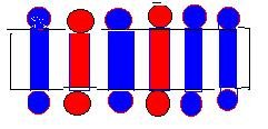
i was thinking about wire bundles on the etd59 but i thought the windings might be to large to go around figuring at 500 mils per amp at 50 amps would need 25000 sq mils using say 24 or 26 gauge wire would need 65 wires in a bundle. the winding in one layer the etd59 has 1.625" of core length and about 0.25" space between the core bobbin and the core legs. blue sec, red primary.
so thats why i thought foil, which barely fit between the legs and the bobbin.
by the way MEGA what is your profession?
thanks
Attachments
jamesrnz said:
i was thinking about wire bundles on the etd59 but i thought the windings might be to large to go around figuring at 500 mils per amp at 50 amps would need 25000 sq mils using say 24 or 26 gauge wire would need 65 wires in a bundle. the winding in one layer the etd59 has 1.625" of core length and about 0.25" space between the core bobbin and the core legs. blue sec, red primary.
Don't worry about current density- It's a myth to design by this rule. It is all about ac resistance in the wire and losses due to this..
switchmodepower said:
Don't worry about current density- It's a myth to design by this rule. It is all about ac resistance in the wire and losses due to this..
ok so the ac resistance-reactance Z- varies by frequency and losses ar e related to the instantaneous reactance a many different points. soooo.... is there some rule of thumb?
jamesrnz said:
ok so the ac resistance-reactance Z- varies by frequency and losses ar e related to the instantaneous reactance a many different points. soooo.... is there some rule of thumb?
Yes you have to calculate losses in the wire. Do you know what your dc resistance is? Start from there. Calc losses in wire and core then calculate temp rise in xfmr. The tricky part is prox effect in the wire/foil.
yeah no load idle 95ma instead of 4.5a with new trans former.
now to put on light load and see about snubbering rc or rcd, primary and rectifiers,, then on to higher currents..............😀 😀 😀
now to put on light load and see about snubbering rc or rcd, primary and rectifiers,, then on to higher currents..............😀 😀 😀
Where is the ground clip of the scope connected?
Do you have a picture of the setup and/or a PCB layout? What is the value of R1, R19, R4, R20? What does the gate drive waveforms look like?
Do you have a picture of the setup and/or a PCB layout? What is the value of R1, R19, R4, R20? What does the gate drive waveforms look like?
ground clips a connected to the ground plane near the transformer.
r1,19,4,20 are 1k.
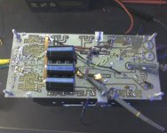
the circuit is a bit messy.
but has come a long way. i have started working on a second board layout that has better ground plane that is connected dozens of places and power traces on one side instead of both sides. the control traces on one side ground plane on the other the output caps on the board multi for low esr.
the series caps ar bypassed at this point i need more capacity than 7uf
i had droop on the switching. so i bypassed it and it squared up. i want them in eventually
the bulk caps might be too big 63v @ 10,000uf (3) black ones
r1,19,4,20 are 1k.
the circuit is a bit messy.
but has come a long way. i have started working on a second board layout that has better ground plane that is connected dozens of places and power traces on one side instead of both sides. the control traces on one side ground plane on the other the output caps on the board multi for low esr.
the series caps ar bypassed at this point i need more capacity than 7uf
i had droop on the switching. so i bypassed it and it squared up. i want them in eventually
the bulk caps might be too big 63v @ 10,000uf (3) black ones
Attachments
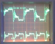
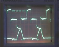
the top one is the output from the gate drive transformer
the bottom is the junction of r2, d5, q1(b), and d5,q1(e),r3 and q3(g)
i had a concern about this but the knee is 5 v then on up to over 10 (sharks fin)
i want to make sure it is not on in the linear portion
the main transistors are fair child HUF75652G3 75a 100v 0.008ohm
to-247 http://www.fairchildsemi.com/pf/HU/HUF75652G3.html which show a low Qc and around 4v on threshold......
the sync is off i think i have to figue out how to delay so the traces sync.
if any of this stuff is wrong i'll try whatever.
Attachments
Isn't Q3 an upper side transistor? Is it measured without bus voltage or did you use a differential connection? The rise and fall time is worrying and not good for high power. Those transistors you use will need very sturdy gate drive to give acceptable performance. The datasheet suggests a 2 ohm gate resistor and the rise and fall times still suck with that, though they will be better than stated at 13V than 50V supply.
It might be possible to remove R3 and the corresponding resistor in all cells and decrease the value of all R2:s. The dischare resistors will probably need to be decreased too. The gate drive transformers will need to have low leakage inductance. Another transformer possibility is driving the low-side transistors directly from the gate drive chips and using a trifilar wound transformer for the upper ones. You could also use 30V or 50V transistors instead and get much easier to drive gates for the same on resistance.
The ringing looks a bit erratic as it is now but this should be because of the discontinous mode. The spikes going beyond supply voltage suggests there are too much inductance in the circuit between transistors and bulk caps though.
yes actually it was q4.
i am out of time for this week have to back to work for 4 weeks. then i'll be back.
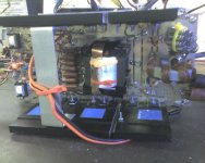
on the new circuit board i have moved around the bulk caps closer to the transisitors. and am thinking about not having a ground plane above the high current traces.
i could parallel to220 transistors.
just for fun i went to 0.7 ohm load and the out put voltage dropped to 9 volts @ 14 amps and the input went to 13 volts at 21 amps. so it doesn't keep up. yet.....i wonder if i could parallel 2 20 amp smps.
if my approach i can change it or frequency, i don't need to tread into unknown territory if it not technically possible..
thanks
i am out of time for this week have to back to work for 4 weeks. then i'll be back.
on the new circuit board i have moved around the bulk caps closer to the transisitors. and am thinking about not having a ground plane above the high current traces.
i could parallel to220 transistors.
just for fun i went to 0.7 ohm load and the out put voltage dropped to 9 volts @ 14 amps and the input went to 13 volts at 21 amps. so it doesn't keep up. yet.....i wonder if i could parallel 2 20 amp smps.
if my approach i can change it or frequency, i don't need to tread into unknown territory if it not technically possible..
thanks
well i am back for a week, and i was looking at voltage drops across pcb traces. and after out last discussion the traces at that frequency do no have enough surface area. 0.5"x0.002".
and the transformer straps from the transformer windings are also too small, 0.5"x0.016".
they would need to also be about 1.5" wide a this current level and freq.
after reading the ti information, i am going to pull the transformer and rewind one with litz wire in the traditional manner so i can come out with the litz wire directly to the transistors n rectifiers without the traces.(I will scrape off the traces) . the 'litz' wire is really 105 wires of number 36 enameled wire.
i will also change the gate transistors to 2 ohms.
i will change the 1k ohm gate turn off resistor to oh........270 or less and watch the effect on the gate turn off.............
any thoughts.......
well well well.
i don't have plasma any more...
megajocke decided i needed bulk caps, imagine that.............that really solved a lot of problems.
i have changes the gate resistors to 2 ohms that helped a lot
i have changed the discharge cap to 180 ohm that helped too
i have changed the emitter base resistor to 10 ohms that squared it up a lot.
i have snubbers going across the primary 0.01 and 3.9 ohms and from the primary to ground plane..
i have 0.01 and 14ohms across all of the rectifiers in the bridge, it is amazing how much rectifier ringing transfer to the primary signal.
on the out put, it holds 17.5 volts until about 15 amps out then the voltage goes down as the load goes up
the pwm is running wide open.
now then i noticed when i reduce the freq from 100 towards 50khz the output voltage comes up when it is loaded??
i have 2 layers (105/36 ga doubled) of three turns for the primary and 2 layers of 6 turns for the secondary. spsp..
1. why does the output power come up with lower freq???
2. how low should i go?
3. do i need a higher turns ratio? reduce pri to 2 turns?
( do have a turn off spike that is kind of high, but within the transisitors range)
jamesrnz said:
1. why does the output power come up with lower freq???
Max duty cycle changes with freq if dead time is constant.
poor eficiency low current out
well things were going well until i added more turns to the secondary.
i was hoping that i would get more current and voltage.
from 3t pri and 6t sec to 3t pri to 9 turns sec?
but that was not the case. it is still stuck at 13 volts at about 23 amps
with about 50a at 13 volts in
i am trying to change on one thing at time, however i notice that there may be flux imbalance since the turn off spikes are not equal.
i have not put in the series caps yet , they would help with the imbalance but would the have a significant effect on the output power?
just a reminder this is a full bridge with 34025 and bridge rect out.
Hi
WHAT the****??? where do you lose 27A??? are you sure you have done everything right? I mean something must heat like heater
Series caps in full bridge is not needed, but do put one, 2.2u should be... well I don't think you can...low voltage and very high current
WHAT the****??? where do you lose 27A??? are you sure you have done everything right? I mean something must heat like heater
Series caps in full bridge is not needed, but do put one, 2.2u should be... well I don't think you can...low voltage and very high current
- Status
- Not open for further replies.
- Home
- Amplifiers
- Power Supplies
- Push-Pull SMPS overshoot problem