No, that's not normal. Is the scope ground connected near the bridge? You will propably see those spikes on the +rail too. Bulk caps are needed at the input. An input filter too probably.
"the transformer is an etd49 with 2 turns 1" wide foil .040, and the secondary is 5 turns foil."
If you need lower transformer losses make sure the 5 turn winding is split up with the primary in the middle. As the thickness is much greater than the skin depth the proximity effect losses will be much lower that way. For a 5 layer winding of 5x skin depth in the same "portion" AC resistance will be about 100 times the DC resistance! If it is divided into two portions AC resistance will be only 10-20 times the DC resistance.
ok,
well i will be back home in a coupl of weeks and after i do all of the 'honey do's' i am going to do a couple of the suggestions.
i will check to see how th scope is connected. which if i remember was from the transformer to the ground plane close by.
thanks i'll let you know........
well i will be back home in a coupl of weeks and after i do all of the 'honey do's' i am going to do a couple of the suggestions.
i will check to see how th scope is connected. which if i remember was from the transformer to the ground plane close by.
thanks i'll let you know........
These spikes are produced by leakage inductances, both from the layout and from the transformer.
ok eva thanks.
i have tried to balance every thing and compact it with minimal turns on the transformer.
i will see what hapoens when i get back in town
thanks
i have tried to balance every thing and compact it with minimal turns on the transformer.
i will see what hapoens when i get back in town
thanks
Put a snubber network parallel over the primary side of your output transformer.
eg 10nF in series with a 3,3 ohm 10 watt resistor.
eg 10nF in series with a 3,3 ohm 10 watt resistor.
i don't have a snubber right now.
i used 40 mil copper foil to handle the current and since the skin effect calculated about 28 mil depth i figured that would be a good compromise
i saw some information about passive feedback snubbers for other topologies but for the bridges ( cap res diode inductor)
i used 40 mil copper foil to handle the current and since the skin effect calculated about 28 mil depth i figured that would be a good compromise
i saw some information about passive feedback snubbers for other topologies but for the bridges ( cap res diode inductor)
Eva said:These spikes are produced by leakage inductances, both from the layout and from the transformer.
How? The spikes should be clamped if there were input bulk caps as this is a full bridge, not push pull.
circuit said:Some more info.
Here is an example of transformer current:
An externally hosted image should be here but it was not working when we last tested it.
Mine is running at 100kHz, that is, a maximum pulse width is 5µs. According to picture above, it goes to peak of 300mA. Is it OK?
I'm using EPCO's transformer ER 11/5 with N87 core. Also tried N49 and T38 - result the same, only with T38 that pulse is slightly smaller.
Anyway, I'm looking for a way to fix this.
Something is saturating... di/dt is supposed to be constant. What flux are you running at?
jamesrnz said:i don't have a snubber right now.
i used 40 mil copper foil to handle the current and since the skin effect calculated about 28 mil depth i figured that would be a good compromise
i saw some information about passive feedback snubbers for other topologies but for the bridges ( cap res diode inductor)
Actually, skin depth at 100kHz is only 8 mils. With 5 layers in one "portion" 8 mil foil will actually have lower losses than 40 mil foil due to proximity effect losses! 5 mil foil would have even lower loss than that! How is the transformer wound now?
On proximity effect losses:
http://focus.ti.com/lit/ml/slup197/slup197.pdf
http://focus.ti.com/docs/training/catalog/events/event.jhtml?sku=SEM401014
megajocke said:
Actually, skin depth at 100kHz is only 8 mils. With 5 layers in one "portion" 8 mil foil will actually have lower losses than 40 mil foil due to proximity effect losses! 5 mil foil would have even lower loss than that! How is the transformer wound now?
On proximity effect losses:
http://focus.ti.com/lit/ml/slup197/slup197.pdf
http://focus.ti.com/docs/training/catalog/events/event.jhtml?sku=SEM401014
I second that. Also with the extra room in the xfmr you can interleave the windings reducing leakage inductance and further reducing the i2r losses.
i'll have to see where skin depth calculation went wrong.
iwas also figuring for current per cirular mils. i could use two foil layers and cut leakage inductane.
mmmmm thanks
since i am a truck driver i dont get to play often
thanks for your patience and understanding
iwas also figuring for current per cirular mils. i could use two foil layers and cut leakage inductane.
mmmmm thanks
since i am a truck driver i dont get to play often
thanks for your patience and understanding
jamesrnz said:i'll have to see where skin depth calculation went wrong.
iwas also figuring for current per cirular mils. i could use two foil layers and cut leakage inductane.
mmmmm thanks
since i am a truck driver i dont get to play often
thanks for your patience and understanding
Keep in mind that you need to interleave with the other winding to reduce leakage. The key is to reduce the distance between primary and secondary.
And Using 2 isolated 5mil foil wrapped together is the same as using 1 x 10mil foil- it does nothing for you.
Do you have a winding construction that you can show? Also what is the output current/voltage?
megajocke said:No, that's not normal. Is the scope ground connected near the bridge? You will propably see those spikes on the +rail too. Bulk caps are needed at the input. An input filter too probably.
"the transformer is an etd49 with 2 turns 1" wide foil .040, and the secondary is 5 turns foil."
If you need lower transformer losses make sure the 5 turn winding is split up with the primary in the middle. As the thickness is much greater than the skin depth the proximity effect losses will be much lower that way. For a 5 layer winding of 5x skin depth in the same "portion" AC resistance will be about 100 times the DC resistance! If it is divided into two portions AC resistance will be only 10-20 times the DC resistance.
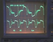
yea! ok the spikes are way SMALL. now i have a better looking full bridge signal. i think i have fought this for a year.
ok as a side bonus the ground and + rail have quieted down a HUGE amount.
my error was the length of the wires from my power supply about 1 meter. and trusting the 2 farad filter caps, but they are to far from the switching circuit, and must create a resonant/ hi voltage drop at the instant the switches turn on and off..................
the input current dropped the output voltage went up as well as the voltage.. better effeiciency..................
now on to snubbering on the primary and the rectifiers.
and maybe rewind the transformer this weekend if i have time.
moral to the story; have big bulk caps as near to the switches as possible, good ground planes with lots of intra-board vias between the ground planes..........

 😀
😀 

Hi guys,
I am having serious second thoughts about that all "microprocessor controlled PSU" thing.. Just want to simplify things down a bit.
I've heard something about a really simple "Royer generator" PSU topology. Simply it is a transformer with multiple primary wingdings and 1-2 transistors.
It looks something like this:
http://www.ctc-labs.de/1mosfetsstc.jpg
http://myfunprojects.com/High efficiency Inverter.html
My google searches are very unproductive on this Royer generator, also haven't found anything on Wikipedia. English isn't my native language, so apparently I am using bad keywords..
Can someone point me to right direction? This is for my personal project AND university's term work, so I need some more theory, calculations etc.
full bridge
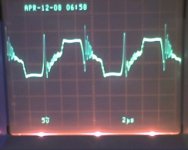
well this is what it looks like now on the primary.
the spike at turn off is much better it was like 90v.
is the ringing during the off time ok to have?
there is some droop is suppose that is because of the series cap.
i need to take care of the ringing on the pos..
well this is what it looks like now on the primary.
the spike at turn off is much better it was like 90v.
is the ringing during the off time ok to have?
there is some droop is suppose that is because of the series cap.
i need to take care of the ringing on the pos..
Hi
Hate to say but it is far from what you should get, I think you will have to lower R, make C high or low enough, depends on how you look at it, to pass as much high freq. as possible, but at same time stop your main freq. Not I am not sure, but if yout input is 12v R should be something like few ohmes
First find only R which "kills" a lot of those oscilations, then add C so that it won't heat R by main freq. only oscilations
- Status
- Not open for further replies.
- Home
- Amplifiers
- Power Supplies
- Push-Pull SMPS overshoot problem