efficiency
well i seem to have the overshoot problem taken care of and working on the pesky little ringing and making progress.
however, the efficiency is only about 58 percent at best and is pretty uniform regardless of load at 17 volts 5 amps to 15 amps but the in put
is high and the transistors get too. warm 13.3 volts at 11 to 34 amps
so i will rewind the transfromer with inter leaving. to see if it makes a difference
megajocke said:
Actually, skin depth at 100kHz is only 8 mils. With 5 layers in one "portion" 8 mil foil will actually have lower losses than 40 mil foil due to proximity effect losses! 5 mil foil would have even lower loss than that! How is the transformer wound now?
On proximity effect losses:
http://focus.ti.com/lit/ml/slup197/slup197.pdf
http://focus.ti.com/docs/training/catalog/events/event.jhtml?sku=SEM401014
i looked over my notes and calculated using 100,000hz instead of 100khz. the formula was asking for khz, and i came up with 0.28 and some how called that 28 mils....
 anyway it should be about 8 mils.... thanks
winding interleaving
ok time for mind loss.....
so what is the proper way for interleaving?
chryssis says two secondaries and one primary, brown says two primaries and one secondary and pressman says 2 primaries and two secondaries.
i am going to rewind tomorrow but?😕 😕
😕
ok time for mind loss.....
so what is the proper way for interleaving?
chryssis says two secondaries and one primary, brown says two primaries and one secondary and pressman says 2 primaries and two secondaries.
i am going to rewind tomorrow but?😕
😕Are you happy with the 2:5 turn relationship? Are 2 turns enough to give reasonable core losses at highest output voltage?
The primary in the middle would be best so you can get the least number of layers in the secondary. Do you have thinner foil? 40 mil foil will give high losses if more than one layer is used. 8 mils is about the best that can be used with a S-P-S layout. Any thicker and the secondary losses will increase a lot due to proximity effect. I'm worried though that 8 mil foil won't be enough for the power you want.
S-P1-S-P1-S-P2-S-P2-S would be much better and I recommend that. With this configuration you won't have a problem with proximity effect losses. Both sides of most turns can be used so 16-20 mil foil would be best here. Thicker would work too but won't reduce the losses much, if at all. The two primaries would be parallelled.
Check out my SMPS:
It is actually working :O
Waveforms:
Order from top:
1. Sinewave on cencondary (output)
2. First end of primary
3. Second end of primary
4. Middle tap of primary (after inductor).
And it is stable enough..
An externally hosted image should be here but it was not working when we last tested it.
It is actually working :O
Waveforms:
An externally hosted image should be here but it was not working when we last tested it.
Order from top:
1. Sinewave on cencondary (output)
2. First end of primary
3. Second end of primary
4. Middle tap of primary (after inductor).
And it is stable enough..
megajocke said:Are you happy with the 2:5 turn relationship? Are 2 turns enough to give reasonable core losses at highest output voltage?
The primary in the middle would be best so you can get the least number of layers in the secondary. Do you have thinner foil? 40 mil foil will give high losses if more than one layer is used. 8 mils is about the best that can be used with a S-P-S layout. Any thicker and the secondary losses will increase a lot due to proximity effect. I'm worried though that 8 mil foil won't be enough for the power you want.
S-P1-S-P1-S-P2-S-P2-S would be much better and I recommend that. With this configuration you won't have a problem with proximity effect losses. Both sides of most turns can be used so 16-20 mil foil would be best here. Thicker would work too but won't reduce the losses much, if at all. The two primaries would be parallelled.
i am using a etd59 (i know i said etd 49 earlier) full bridge.
i do have 10mil, 16 mil and 40 mil foil.
i planned on about 500mil per amp.
i used about 1500g for my calculation for primary turns. would like to use less on the secondary but i am not sure the voltage/ will make it. in theory land 2:3 turns should do it but....
do you have a reality suggestion for pri turns?
running from 12v batteries i planned for a 1 volt loss to the transistors at a low of 10v , when the battery is about dead. to get about 15 volts @ 40 amp to the motor after the rectifier loss inductor relay and wire losses on the load side.
i would like at least 70 percent 80 would be best. i/o efficiency.
thanks MEGA
What is your freq and power? 50KHz-100Khz use only 8-10 mil foil. Anything higher only increases your ac resistance due to prox losses, regardless of winding geometry.
The interleaving that megajocke suggested looks pretty good.
The interleaving that megajocke suggested looks pretty good.
I get a delta-B of 160mT (1600G) for 12V in and 100kHz. This is +-80mT pk. Depending on core material and allowable core loss 1 turn might actually work for a peak flux of 160mT at 100% duty and 12V in but won't give you much flexibility in turns ratio.
If I didn't miscalculate it seems the DC resistance of 1 turn of 16 mil foil is about 0.14mOhms if the strip width is 32mm (area=13 square mm) and length of turn 106mm.
For the S-P1-S-P1-S-P2-S-P2-S configuration this gives a total primary DC resistance of 0.14mOhms and a secondary resistance of 0.7mOhms. AC resistance is not much higher for the fundamental. The harmonics will see a bit higher resistance but not something extreme as will be the case with multiple
You'll have to calculate worst-case RMS current in primary and secondary to see if this is good enough. 50A RMS in the secondary will give ~2W of losses in the secondary and ~1W in the primary. If it isn't too messy to construct in reality I'd try making it like S-P1-S-P1-S-P2-S-P2-S. The secondary could be wound in one continous strip if done like this. I assume there is no need for high voltage insulation between primary and secondary.
Where are your biggest heat problems right now?
switchmodepower said:What is your freq and power? 50KHz-100Khz use only 8-10 mil foil. Anything higher only increases your ac resistance due to prox losses, regardless of winding geometry.
The interleaving that megajocke suggested looks pretty good.
If the primary and secondary are interleaved like S-P1-S-P1-S-P2-S-P2-S then there will be only half a turn per portion so 16 mil foil or a bit thicker can (and should) be used. 🙂 The outer turns on the secondary will only have 8 mils used for conduction though.
If done like SS-PP-SSS then you are right that thinner foil should be used. This probably won't do at the power he want's though.
It should look like this:
Attachments
megajocke said:
If the primary and secondary are interleaved like S-P1-S-P1-S-P2-S-P2-S then there will be only half a turn per portion so 16 mil foil or a bit thicker can (and should) be used. 🙂 The outer turns on the secondary will only have 8 mils used for conduction though.
If done like SS-PP-SSS then you are right that thinner foil should be used. This probably won't do at the power he want's though.
It should look like this:
100khz, i have tyvek transformer insulation about 6 mils
also i have only one sec output so .
also calc'd 1 turn but for step up ratio i opted for 2 on the primary so my step up will be 2.5 ish.
so if i use 16mil say, spsps or spsp?
the switching transistors get real warm, they are next to the parallel Schottky's
intersting..
thanks
spsps will be better but this will just be 1.5 times step up. (or 3 times if the primary turns are parallelled which should work if you want 3 times and the core losses aren't too high like this) If you do spspspsps you will get the 2.5 times step up.
If the transistors are getting hot it could be conduction losses, cross-conduction or avalanche. Did you put in local bulk caps and got rid of the spikes?
If the transistors are getting hot it could be conduction losses, cross-conduction or avalanche. Did you put in local bulk caps and got rid of the spikes?
megajocke said:
If the primary and secondary are interleaved like S-P1-S-P1-S-P2-S-P2-S then there will be only half a turn per portion so 16 mil foil or a bit thicker can (and should) be used. 🙂 The outer turns on the secondary will only have 8 mils used for conduction though.
If done like SS-PP-SSS then you are right that thinner foil should be used. This probably won't do at the power he want's though.
It should look like this:
Ooo. Fields are split, my mistake. Yes for the ones in the middle it would be double and the outer ones (of P1, P2) 8 mil will suffice.
Yeah, but it won't hurt either having them 16 mils all the way. Should be easier to wind that way not having to join 8 mil foil onto the ends. The whole secondary can be one long strip.
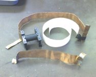
The picture shows how it could be done if seen from the side of the core. Green is secondary, red and purple are the primaries that are to be parallelled. Secondary and primary leadouts should be on the same side of the core or else there will be some portions with 2 layers which is not very good for the losses.
The picture shows how it could be done if seen from the side of the core. Green is secondary, red and purple are the primaries that are to be parallelled. Secondary and primary leadouts should be on the same side of the core or else there will be some portions with 2 layers which is not very good for the losses.
Attachments
yep the bulk caps took care of the spikes and brought up the positive pulse. waveforms on post 37 and 38.megajocke said:spsps will be better but this will just be 1.5 times step up. (or 3 times if the primary turns are parallelled which should work if you want 3 times and the core losses aren't too high like this) If you do spspspsps you will get the 2.5 times step up.
If the transistors are getting hot it could be conduction losses, cross-conduction or avalanche. Did you put in local bulk caps and got rid of the spikes?
i am not understanding how you are getting the step up. i may have a major misunderstanding in winding with foil.
i wound the secondary five turns and brought out strips then wound 2 turns and brought out strips from the turns.
i thought then i should run another secondary over those and parallel them.
sp vs sps, however i think i do not under stand how you are stepping up 2.5 by parallelling spspspsps ?
😕 😕 😕
Attachments
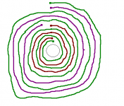
Look at that spiraly thing I made and I think it should be clear. (If you don't get dizzy) 😉 There are one five turn secondary (green) and two two turn primaries. (red, violet)
If wound sssss-pp-sssss like you suggest only 8 mils of thickness of the primary turns will be used. The outer 8 mils of each secondary turn except the outermost ones will have current flowing in different directions. Say 1A is flowing through each 5 turn secondary: The outer turn will have 1A flowing in the inner 8 mils. The turn inside of that will have 2A flowing on its inside and 1A flowing in the _wrong_ direction on the outside. The turn closest to the primary will have 5A flowing in the right direction and 4A flowing in the wrong direction! Losses will be insane! 😱
If wound sssss-pp-sssss like you suggest only 8 mils of thickness of the primary turns will be used. The outer 8 mils of each secondary turn except the outermost ones will have current flowing in different directions. Say 1A is flowing through each 5 turn secondary: The outer turn will have 1A flowing in the inner 8 mils. The turn inside of that will have 2A flowing on its inside and 1A flowing in the _wrong_ direction on the outside. The turn closest to the primary will have 5A flowing in the right direction and 4A flowing in the wrong direction! Losses will be insane! 😱
megajocke said:Look at that spiraly thing I made and I think it should be clear. (If you don't get dizzy) 😉 There are one five turn secondary (green) and two two turn primaries. (red, violet)
If wound sssss-pp-sssss like you suggest only 8 mils of thickness of the primary turns will be used. The outer 8 mils of each secondary turn except the outermost ones will have current flowing in different directions. Say 1A is flowing through each 5 turn secondary: The outer turn will have 1A flowing in the inner 8 mils. The turn inside of that will have 2A flowing on its inside and 1A flowing in the _wrong_ direction on the outside. The turn closest to the primary will have 5A flowing in the right direction and 4A flowing in the wrong direction! Losses will be insane! 😱
switchmodepower said:What is the output power? Maybe you can do this with wire.
MEGA ,?maybe thats where my current is going, don't ya just hate those loud mouth beginners?
Switch, 10-14 volts at 50-60 amps in and 8-20 volts out at up to 40 amps.
thanks
Now that there is talk about push-pull transformer winding, I would like to ask what is the optimal way to wind a twin-secondary push-pull transformer for 12V input and 4+4:21+21 winding ratio, I am planning on using wire and something like an ETD34-core where I probably will use one winding layer per primary or secondary.
Should I place P1 and P2 closest to the core since these will carry the highest current, and place the secondaries S1 and S2 on the outmost layers? The transformer will also carry a small 4+4 winding that will clamp the inductive spikes from the primaries, but with small average current, guess this should go on the outmost layer?
Should I place P1 and P2 closest to the core since these will carry the highest current, and place the secondaries S1 and S2 on the outmost layers? The transformer will also carry a small 4+4 winding that will clamp the inductive spikes from the primaries, but with small average current, guess this should go on the outmost layer?
ok today i will try this.
i paralleling the primaries the inner most of each primary will be connected together and the outer most of each will be connected together.
the phasing for the pri to sec is not important?
i think i will use 8 mil for each pri and 16 mil for the sec.
i suppose my snubbering will change now.
as a side note the leakage inductance could be measured by shorting the secondary and measuring the pri inductance?
i know about vacuum tube switching supplies in research, radar and satelite power supplies, megawatt low freq switching.. this is way different and not all of the principles seem to ttransfer...............
- Status
- Not open for further replies.
- Home
- Amplifiers
- Power Supplies
- Push-Pull SMPS overshoot problem