Well Dave, since you said>> In certain cases etc. <<< it raises a new question concerning say the Carver amps that claim to use this back EMF into their feedback loop and this is supposed to provide a sort of information for the amp to adjust to the listening environment. This idea threw my brain into a tailspin, and so this subject, as offhand as it seemed made it go to that question. I do not know any more specifics about the design mentioned. Has this ever been done before, and is it effective?
that claim to use this back EMF into their feedback loop
I’m no expert but is that not something to avoid?
dave

Yah, when I read that, it would seem that Bob is onto one of his unusual designs. Actually using something that is to be shunned by others for the benefit of your own design. Dunno. Never knew that much about amps.
If the speakers are connected in series and have large high inductance voice coils you can get the EMF big enough to move the other woofer. A quick push generates a higher voltage than a slow push. You can see an example of voltages generated if you drive one voice coil of a dual VC woofer and measure the other.
All the current in a series circuit flows in the same direction (say, CW or CCW). Its only the voltages across the drivers that will be in opposite phases.Since one is the generator and the other the load, the current in them runs in opposite directions.
Let's assume the drivers are 10" cone woofers with 2" diameter voice coils.
Another interesting point is if we press the cone and hold it for a few seconds, will the other cone move (same or opposite direction is still being debated) and stay stationary until we release the first cone?
To my understanding, the back EMF occurs only when there is relative motion between the voice coil and the magnetic field.
It may help to draw a schematic of the circuit. Maybe label the terminals on a speaker as red and black, or whatever. Then just work out the problem. One is a generator and the other is a load.
The other cone will only move when there is EMF flowing. This means only when the cone being pushed is moving to create that current. Once the cone being push stops moving the second cone will return to rest as there is nothing flowing to keep it away from the resting positoon. You can hold the primary cone in or out but it will have no effect until it moves again. It’s the current generated by moving the voice coil in a magnetic field that makes current flow. No movement no flow. No flow no movement in the second speaker.
With two devices in parallel, the voltage across one cannot be in opposite phase to the voltage across the other. I think your logic is flawed, unless you want to rewrite a bit of physics ;-)All the current in a series circuit flows in the same direction (say, CW or CCW). Its only the voltages across the drivers that will be in opposite phases.
Jan
Yes.Won't the back EMF oppose the change causing it,
At terminals, back EMF and supply EMF are at same polarity.and therefore be of the opposite polarity to the applied voltage?
So, when they are equal current is zero, beacuse theres no voltage difference beetween them. Like two equal-voltage batteries connected in parallel. Current wont flow.
Last edited:
Of course it can. If one speaker cone is pushed in then it is acting as a generator. Inside a generator, aka voltage source, current flows from negative to positive. Outside of a voltage source current flows from positive to negative. Its also true that if the speakers in parallel are disconnected from other circuitry, there is only one current loop. The current is the same direction, amplitude, and phase for every device in that loop.With two devices in parallel, the voltage across one cannot be in opposite phase to the voltage across the other.
Maybe think about it this way: If a battery and a light bulb are connected in a parallel and there is no other circuitry then there is only one current loop. Essentially the two devices are connected both in series and in parallel. Its just a matter of which way you choose to look at it. Inside the battery current flows from negative to positive. Outside the battery current flows from positive to negative.
Last edited:
Stop tapdancing. The bulb on the battery has exactly the same voltage on the bulb as on the battery. They are hard wired together.
As are two drivers connected in parallel.
You know, this kind of BS was the reason I left diyaudio. After two days, the BS peddlers swarm back again.
Don't you have any self-respect??
Jan
As are two drivers connected in parallel.
You know, this kind of BS was the reason I left diyaudio. After two days, the BS peddlers swarm back again.
Don't you have any self-respect??
Jan
Let's take a dual voice coil woofer, with its coils connected parallel, but otherwise left open. Now push the diaphragm. It will move freely, because the voltages in the two VCs are equal in magnitude and polarity. If it weren't so, the diaphragm would resist to pushing in.
This is exactly the case with two separate woofers connected parallel. One follows the other (induced EMF or externally applied voltage, does not make any difference).
This is exactly the case with two separate woofers connected parallel. One follows the other (induced EMF or externally applied voltage, does not make any difference).
Its you who doesn't know what you are talking about, not me. I have been trying to be polite while you prefer to be rude....two drivers connected in parallel.
It doesn't even matter if the speakers are connected to a power amp and the amp has infinite damping. So long as the speaker cable has some resistance pushing in on one cone will cause the other cone to move, even if only very slightly.
Its just the same as if a battery were put in parallel with one driver. The speaker cable would act as a load on the battery as would the driver. The battery also has internal resistance which would cause some voltage drop, so that the net battery terminal voltage might be one polarity or the other. Most of the battery current would flow through the speaker cable to the amp output which is essentially another voltage source, and thus a ground by superposition. Some battery current would also flow through the driver, causing some even if very slight motion.
OTOH if the amp were turned off and its output was in a high impedance state, the driver and battery would still be connected up the same. You call it parallel. Now it looks much closer to the battery and driver being in series. Any current though the amp has become negligible. Series or parallel is just a human concept, and in this case you can look at it either way.
EDIT: Regarding leaving diyaudio, maybe you should not be here if you can't or won't comply with the rules.
Last edited:
The above part was wrong for what I was trying to illustrate. Too late to edit it. The rest is correct. To continue then, if the speaker is unplugged from the amp, and if we are still using a battery as the model for a driver acting as a generator, the battery and the driver are still wired up the same way they always were. Now there is only one possible current loop. The currents all flow around the loop in the same direction, call it CW or CCW.so that the net battery terminal voltage might be one polarity or the other.
Going back to your initial claim:
It depends what you mean by that. When one driver is the generator, the current flows around the loop in only one direction. However, the current inside the generator/driver flows from negative to positive, whereas the current in the load flows from positive to negative....the current in them runs in opposite directions.
That is different from if the amplifier is the generator. In that case both drivers are loads and the current in both drivers flows from positive to negative. Thus the generator/driver current direction when it is acting as a load is reversed from the case where the generator/driver acts as the generator. Is that what you were trying to say? If so, I believe that would be correct.
Last edited:
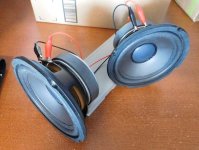
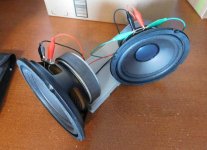
Two 6.5" woofers wired in parallel.
Push one woofer in, the other moves out. However you need to quickly push ~10mm in to get ~2mm out of the other. One acts like a generator (speed and distance are important) and other acts like an inefficient motor. This electrical movement is minor compared to an inter-chamber air leak which nearly 1:1.
Connecting a low impedance path between them (amplifier, green wire, short, etc), stops the motion completely.
Attachments
Push one woofer in, the other moves out.
A diagram (as I suggested in post #2) may help visualise this:
If the cone of the top driver is pushed inwards, an EMF is induced which opposes the cone movement.
Think of that EMF as being directed in the opposite direction to the cone movement, i.e., 'outwards'.
The bottom cone will then be subject to this 'outwards' EMF, so will move outwards, i.e., in the opposite direction to the top cone.
This explanation would certainly be in line with DonVK's experimental results.
Okay, I just did an experiment too. I connected the + end of a 1.5v AA cell to one terminal of a speaker (let's call it the red speaker terminal) and the - end of the battery to the other speaker terminal. The cone moved in. There was also a DVM attached to the speaker terminals with the same polarity as the battery (red meter lead to the + end of battery, and to the red speaker terminal). Then I disconnected the battery negative terminal. Pushing in on the cone produced a + voltage on the meter (again, the red terminal). While I let the cone return out to the rest position the meter showed a negative voltage. Thus what changed was the direction of current through the speaker when it is a generator. The voltage polarity for the cone moving in stayed the same in both cases.
Therefore if another speaker were connected in parallel, while I was pushing in the cone on one speaker (while it was in motion), a + voltage would be applied to the corresponding (red terminal) of the other speaker. IOW, the other speaker should move in too.
Therefore if another speaker were connected in parallel, while I was pushing in the cone on one speaker (while it was in motion), a + voltage would be applied to the corresponding (red terminal) of the other speaker. IOW, the other speaker should move in too.
Last edited:
Therefore if another speaker were connected in parallel...
Did you actually try that?
DonVK did and disagrees with you.
- Home
- Loudspeakers
- Multi-Way
- Push one speaker in, the other goes out