Hmm, for me clipping is the cause, the harmonics the effect.Also, clipping of course is harmonic distortion ... so distinguishing makes no sense here.
It is easily audible that is for sure.
ChatGPT giving nice worded text does not make it more trustable. Leaving sources out is for me reason to distrust it.

ChatGPT is still just a baby....don't be cruel to him. 🙂
Soon he will grow and with planetary processor resources he will evolve in unimaginable ways....and then he could come back to all the people which were not nice to him. I can't imagine what will happen when he enters puberty...😱
Waiting for further development of hifijim's speakers... 🙂
Soon he will grow and with planetary processor resources he will evolve in unimaginable ways....and then he could come back to all the people which were not nice to him. I can't imagine what will happen when he enters puberty...😱
Waiting for further development of hifijim's speakers... 🙂
I have no concerns about being off topic. As the thread grows, I will add an index in the first posting to aid anyone who reads it in the future.
Back in my school days we learned to measure sound power in a (fully) reverberant room. We didn't have Klippel NFS in these days.And I thought that sound power was measured in a full anechoic environment, not a hemi-anechoic one...
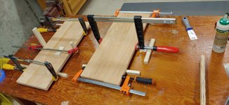
I am in the process of gluing up cherry boards into panels which will clad the midrange box. I got a good deal on cherry lumber with some moderate knots and defects. Since I will need multiple small panels of 8 to 11 inches, I have no problem dealing with knots and defects. I got 25 bd-ft of 4/4 S2S for $100.
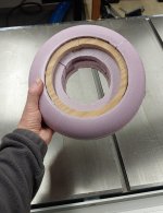
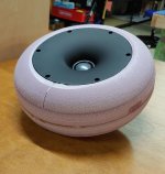
I finished fabricating the prototype tweeter housing, and measurements will begin tomorrow. I made two jigs for this construction, a circle cutter for the band saw, and a guide for the router which will enable me to safely use the large 37 mm round-over bit on a circular workpiece. Developing these jigs is actually more important to me than the acoustical measurements.
Normally when I mount a driver in a foam board, I use #8 machine screws with a fender washer and a nut on the back side. However with this prototype, it would be very cumbersome (virtually impossible) to get access to the back side of the driver holes. So instead, I recessed a plywood ring and glued it in place, and I will screw the driver to this plywood.
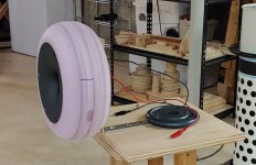
Although the prototype looks like a pink tire 😆, I am hopeful that the same shape in laminated cherry will look quite a bit better…
j.
I finished fabricating the prototype tweeter housing, and measurements will begin tomorrow. I made two jigs for this construction, a circle cutter for the band saw, and a guide for the router which will enable me to safely use the large 37 mm round-over bit on a circular workpiece. Developing these jigs is actually more important to me than the acoustical measurements.
Normally when I mount a driver in a foam board, I use #8 machine screws with a fender washer and a nut on the back side. However with this prototype, it would be very cumbersome (virtually impossible) to get access to the back side of the driver holes. So instead, I recessed a plywood ring and glued it in place, and I will screw the driver to this plywood.
Although the prototype looks like a pink tire 😆, I am hopeful that the same shape in laminated cherry will look quite a bit better…
j.
Attachments

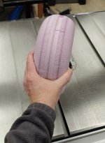
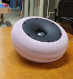
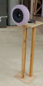
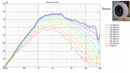
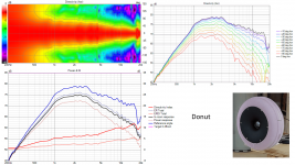
I have competed measurements of the latest prototype. My wife calls it the donut, and the name has stuck…
The responses look good to me. It is slightly different than the beveled box prototype (post #2), but I am not sure that one is better than the other, either would make a fine enclosure for this tweeter. I believe the donut has a slightly more manageable response from 1.5k to 3k, on-axis, ER, and power response… but it is close.
I also included a comparison response of the flat panel (post #37 - 41).
I have some odd little resonances at 2.5k and 4.5k. They show up in the polar responses and also in burst decay and CSD plots. The burst decay reveals additional smaller resonances between 5k and 10k. I believe these are coming from the foam board enclosure. I have seen this before with XPS foam board structures. The density is so low and the stiffness to weight ratio is high enough that the resonances are typically above 1k. The material has a lot of internal damping, so the resonances decay quickly, but on the other hand the mass is very low, so a small amount of stored energy does result in a significant acoustic radiation. Nonetheless, XPS foam is a great material for quickly whipping up prototypes.
Attachments
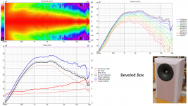

I would agree that they both look good. When nitpicking I would choose the beveled box because the directivity transition is smoother overall without levelling out like the donut does. The traces are more separated in general, only the 10K area is more problematic but not in any way to worry about.The responses look good to me. It is slightly different than the beveled box prototype (post #2), but I am not sure that one is better than the other, either would make a fine enclosure for this tweeter. I believe the donut has a slightly more manageable response from 1.5k to 3k, on-axis, ER, and power response… but it is close.
I tried to smooth out the last bit by starting the curve right at the driver edge to leave no flat baffle in this design. Harder to make for sure.
Attachments
I was thinking MDF with an automotive wrap. I suppose ply core and solid wood edges like Jim would still be possible just more complicated. All pie in the sky until I make time to finish the CNC though.
Fluid - regarding your design in post#67: the transition from the flat baffle surface to the rounded profile seems like a very shallow angle at first. Could you show a cutaway view at the tweeter?
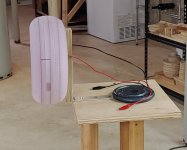
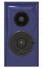
I would like to make my tweeter housing in a tear-drop shape, both for performance and aesthetics. at the front it would be identical to my donut, but the back would taper down in teardrop shape, rather than rounded over like the front. However, I am scratching my head to figure out a reasonable way to construct this. The best way would be to buy a lathe and learn how to use it, then turn the shape... i have never run a wood lathe, and I doubt I would find much use for this tool after this project.
I would like to make my tweeter housing in a tear-drop shape, both for performance and aesthetics. at the front it would be identical to my donut, but the back would taper down in teardrop shape, rather than rounded over like the front. However, I am scratching my head to figure out a reasonable way to construct this. The best way would be to buy a lathe and learn how to use it, then turn the shape... i have never run a wood lathe, and I doubt I would find much use for this tool after this project.
Hifijim, if you do get to 3D printing you can squeeze the last bit of diffraction out from the device with ATH and BEM sims. Utilizing continuous curve all the way from throat to tip of the backside does it.
Mabat provided new visualization for ABEC data which triggered / allowed the last minute diffraction optimization as the resolution was now good enough to see a difference 😀 Discussion starts here if you dive into it https://www.diyaudio.com/community/...-design-the-easy-way-ath4.338806/post-7220732 . Further on there is option added to shape the backside independently, tips how to zone into good shape and perhaps more importantly just some background discussion to help you navigate your project forward as you see suitable.
Since the visible trace of edge diffraction is already quite small, even with hand shaped and guestimated roundover like with your donut, I'm not sure if there is further audible difference and is for everyone to find out themselves. However, 3D modeling and printing cost is about the same no matter what the shape is so I see no point going for anything else than top performance / preferred visual looks. Perhaps more important than the miniscule diffraction optimization you might benefit from BEM sims to optimize the crossover region as well, besides size and shape of the tweeter construct there is size and shape of the woofer box that affects.
Last edited:
It is elliptical in cross section, something close to a golden ratio of height and width based on the thickness of the baffle.Fluid - regarding your design in post#67: the transition from the flat baffle surface to the rounded profile seems like a very shallow angle at first. Could you show a cutaway view at the tweeter?
I think with the right jigs and angle of router bit you could make something like that out of wooden circular sections. A final finish could be made out of a makeshift drill jig to turn it and sand it smooth.I would like to make my tweeter housing in a tear-drop shape, both for performance and aesthetics. at the front it would be identical to my donut, but the back would taper down in teardrop shape, rather than rounded over like the front. However, I am scratching my head to figure out a reasonable way to construct this. The best way would be to buy a lathe and learn how to use it, then turn the shape... i have never run a wood lathe, and I doubt I would find much use for this tool after this project.
I think sometimes people don't give full consideration of the overall effect of trying to remove all diffraction. An infinite baffle has no diffraction but it also has much less directivity. That might be a good or bad thing depending on the design. Making things in sections without full consideration of how that will fit into the overall system can lead to disappointment.
If you can make a paper template that fits the curve of the waveguide and can get a reasonably accurate dimension of the dome and surround height and width, I can simulate you a few options to see how they differ.
Yeah especially considering how much more effort there is trying to optimize every bit of it, perhaps the effort would be worth more somewhere else in the process.I think sometimes people don't give full consideration of the overall effect of trying to remove all diffraction. An infinite baffle has no diffraction but it also has much less directivity. That might be a good or bad thing depending on the design. Making things in sections without full consideration of how that will fit into the overall system can lead to disappointment.
Its interesting topic however. The two are not mutually exclusive, diffraction and directivity. Diffraction has effect on directivity but the same directivity can be achieved "without" diffraction by increasing size of the system (for example bigger wave guide) so the choice is more like what the room acoustics are and aesthetics. "Without" is in quotes as there is some no matter what except in infinite baffle 🙂
Its all about what is audible and what is not, there is no need to be afraid of diffraction if it doesn't harm the sound. I've got no idea which is more audible: some diffraction with positive effect in the DI with steady state stimulus, or the fact that diffraction comes temporally wee bit later than direct sound. Perhaps the DI is more important one as long as there is some attention to edge diffraction. Like any with any compromise there is no need to go further than necessary, sweet spot gives best result. What the sweet spot is in this case, perhaps listening tests would tell.
Last edited:
I was speaking only of the shape behind a waveguide or baffle as that was the context. Without diffraction there is no directivity in that case. Controlling the diffraction to produce a desirable result seems more useful to me than eliminating it. But if the aim is to lower the DI of the system then it makes sense.The two are not mutually exclusive, diffraction and directivity.
Me too, see this example on freestanding waveguides in the ATH thread. For example ST260 waveguide is relatively small as diffraction helps with directivity on the low end. Adding rounded back the diffraction goes away and bigger radius is needed to maintain the DI to low frequency. Basically diffraction enables (considerably) smaller device for particular DI. Difference is in how fast the DI rises.
ps. the device in the link has low DI, but it doesn't have to, it could be high DI device like ST260. The difference of backside / diffraction is in the slope where DI transitions from 0 to "target", diffraction eliminated the slope is "natural" and very slow, while diffraction jacks DI up fast. Perhaps high DI system is better with faster slope? I mean, hard to achieve with shallow DI slope. Conversely, like you say, if its low DI system one could use low diffraction device.
ps. the device in the link has low DI, but it doesn't have to, it could be high DI device like ST260. The difference of backside / diffraction is in the slope where DI transitions from 0 to "target", diffraction eliminated the slope is "natural" and very slow, while diffraction jacks DI up fast. Perhaps high DI system is better with faster slope? I mean, hard to achieve with shallow DI slope. Conversely, like you say, if its low DI system one could use low diffraction device.
Last edited:
Thanks, I appreciate that.If you can make a paper template that fits the curve of the waveguide and can get a reasonably accurate dimension of the dome and surround height and width, I can simulate you a few options to see how they differ.
Before I proceed in any direction, I need to do some more simulations with the data I have gathered.
@vineethkumar01 , @tktran303 , @tmuikku - - I appreciate all of your thoughts. Thank you.
j.
- Home
- Loudspeakers
- Multi-Way
- Purifi + Waveguide Project