I know, lol, I am only 4 pages in the manual and don't know if I can withstand several reads, and I don't even want to operate it, I just want to be able to que in on some plot discussions here. Aside from precision, it's lookin next to impossible.Is that the easiest one ?
The precision of many aspects of different simulators tends to be similar. For example the electrical simulations are generally quite accurate. Simulation of cone breakup is usually non-existant. Simulation of baffle effects is more medium accuracy.
I can tell you what i use, but that is not necessarily what I would recommend to a new designer just getting started on the learning curve.Would anybody give me a list of PROGRAMS that are involved
Acoustical measurements require a test microphone, which usually means a small capsule omnidirectional microphone with a calibration file. Entry level measurement microphones are about ~ $80. You can use a USB microphone which plugs directly into a laptop, or you can use an XLR-connection microphone. The USB option has the advantage of being simple, plug and play, and fewer opportunities to mess up the measurements. The XLR-connection mic will require a USB audio interface. The USB option can serve you well for a time, but eventually your skill and knowledge will progress to the point where you will want more data than it can supply. At that point you will have to switch to an XLR-mic and a 2 channel audio interface. Only you can assess your technical skill and knowledge and judge which type of mic you should start with.
I started with a Dayton Omnimic, which has its own measurement software. When I decided I wanted to do full polar measurements to support a more robust simulation, I bought a Berringer UMC202HD USB audio interface, and an Audix TM1 microphone.
I use ARTA for acoustical measurements. It is not free, but the liscensing fee is modest. Other people use REW, which as far as I know is free.
I am not an expert on impedance measurements. I know there are inexpensive ways to measure impedance that T/S parameters, but I use the Dayton DATS v3 for this.
For simulation, I use VituixCad. It is free. It is very powerful. I love this software. BUT...The program is designed for people who already know what they are doing. It is not a learning tool, and the users' guide is a reference, not a tutorial. If you have not done speaker design before, starting with VituixCad would be like trying to study calculus without have learned algebra, geometry, and trigonometry first. However, some novice designers have successfully worked through the Vcad complexity, so once again only you can assess your technical skill and knowledge and judge how you should proceed. I would expect that an electrical engineer (with no speaker design experience) would move faster up the Vcad learning curve than a car salesman (with no speaker design experience).
I am not the right person to recommend alternatives to VituixCad (such as WinSD, boxsim, soundeasy, others). This thread https://www.diyaudio.com/community/...-design-your-own-speaker-from-scratch.332688/ discusses a lot of software options. I can recommend Xsim as a good learning tool. Xsim is a free crossover circuit simulator. It simulates the response of the speaker on one axis, but for a beginner, focusing on one axis is not a bad way to learn.
I hope this helps... 🙂
j.

I think I will start here because I basically have arithmetic knowledge, and can kind of understand physics calculus operations, somewhat, but mainly the theory, not the calculations. In looking at citing some theory for you without the mathmatical representation that I have looked into I came across ring modulation, which has some linking details into signal processing and associating variables. This can direct me on some information and lingo here. A one dimensional axis seems ideal to for foundation too.I can recommend Xsim as a good learning tool. Xsim is a free crossover circuit simulator. It simulates the response of the speaker on one axis, but for a beginner, focusing on one axis is not a bad way to learn.
Many thanks.
Might you have a suggestion for an app that I can utilize with my phone. I entertain brief thoughts of reaching a build that has instrumental designs into a speaker. It's a nice imagination, but the notation behind that is a joke for me. Which a sense of humor is always appreciated too.
Thanks again
At this point I don't necessarily want to build a speaker, and facing reality I am behind the curve to ever do so; however, I appreciate your suggestion as I hope to understand discussions here, at very least.
I have a few components that I am happy with. They include pass labs xa 100.5 monoblocks, adcom gfp-750 preamp, Mcintosh mr 77 tuner, and Joseph Audio Perspective 2 speakers. It's a beautiful combination, but I sometimes lose focus in listening and want to take some measurements and see if there might be dependant variables with my operation. Most of my intrest is in thermal dynamics in light mediums reaching into sound manipulation. To put it plainly, I want to have some analysis to see if things like disco balls or room treatment changes effect personal biometrics and the interrelationship. A plausible humorous mouthful, I know. Lol So basically, could you SUGGEST APPS for a phone or a BASIC INSTRUMENTs that could start me in a scientific methodology that I might but don't necessarily need to record and assist a rudimentary study from which I might draw correlation. Appreciate it again.
I have a few components that I am happy with. They include pass labs xa 100.5 monoblocks, adcom gfp-750 preamp, Mcintosh mr 77 tuner, and Joseph Audio Perspective 2 speakers. It's a beautiful combination, but I sometimes lose focus in listening and want to take some measurements and see if there might be dependant variables with my operation. Most of my intrest is in thermal dynamics in light mediums reaching into sound manipulation. To put it plainly, I want to have some analysis to see if things like disco balls or room treatment changes effect personal biometrics and the interrelationship. A plausible humorous mouthful, I know. Lol So basically, could you SUGGEST APPS for a phone or a BASIC INSTRUMENTs that could start me in a scientific methodology that I might but don't necessarily need to record and assist a rudimentary study from which I might draw correlation. Appreciate it again.
My bad, 👍Brother,
Way OT.
Please start a new thread…
Designing crossover filters for waveguides tweeters is a little different than doing so for flat baffle tweeters. Because of this, I have been practicing with the measured response of this tweeter. It has been interesting. First a bit of background on the two earlier systems which both used flat-faced tweeters.
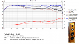
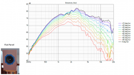
The first graphic shows the Power and DI response of the BT8 system. This system was designed with a minimal baffle around the tweeter, and a 1.2x wavelength CtC distance between mid and tweeter. Preliminary simulations had shown that this would work well, and it did. After collecting vertical and horizontal polar responses of each driver, the simulation demonstrated that almost any crossover topology would work well. I am showing the result with a 4th order 2 kHz crossover, but 2nd and 3rd order worked well, and any crossover frequency from 1.8k to 2.4k resulted in a good response. The goal of this speaker was a flat on-axis response, and a DI response which was flat from 300 Hz to 5 kHz, then rising from 5k up, and any combination of 2nd, 3rd, or 4th order filters from 1.8k to 2.4k achieved a +/- 1 dB on axis AND the target DI within +/- 1 dB.
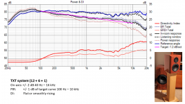
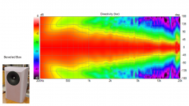
The second graphic shows the TXT system with the current crossover filter. This system has a larger baffle around the tweeter, and a CtC spacing of about 0.75x wavelength from mid to tweeter. The goal of this filter is to optimize the Predicted In Room response. The target PIR was -1.2 dB per octave, and this filter achieves that goal within +/- 1 dB. However, it was challenging to get to this point, and I had to allow some increased variation in the on-axis and listening window curves. Getting good all-aspect performance from this system required balancing a lot of tradeoffs. The only filter that really worked is a 3rd order at 1.8k.
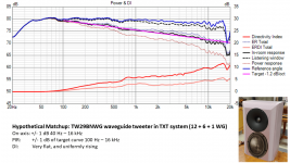
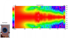
The third graphic represents a hypothetical matchup, a thought experiment. What would happen if I could replace the flat-faced tweeter response of the TXT system with the measured waveguide tweeter? The cabinet width of the TXT system and the foamboard prototype are close, so it’s a valid hypothetical.
In this case it is easy (almost too easy) to achieve excellent simulation results. The on-axis curve is very flat, and the PIR curve matches the target -1.2 dB/octave. The filter between mid and tweeter is 4th order at 1.6k but other combinations worked well. The woofer to mid is at 200 Hz as before.
Of course the radiation pattern of the Purifi will not exactly match the MW16TX-4, and the cabinet differences will shape things also. But it is an interesting hypothetical. It illustrates why waveguides have become popular among designers.
The first graphic shows the Power and DI response of the BT8 system. This system was designed with a minimal baffle around the tweeter, and a 1.2x wavelength CtC distance between mid and tweeter. Preliminary simulations had shown that this would work well, and it did. After collecting vertical and horizontal polar responses of each driver, the simulation demonstrated that almost any crossover topology would work well. I am showing the result with a 4th order 2 kHz crossover, but 2nd and 3rd order worked well, and any crossover frequency from 1.8k to 2.4k resulted in a good response. The goal of this speaker was a flat on-axis response, and a DI response which was flat from 300 Hz to 5 kHz, then rising from 5k up, and any combination of 2nd, 3rd, or 4th order filters from 1.8k to 2.4k achieved a +/- 1 dB on axis AND the target DI within +/- 1 dB.
The second graphic shows the TXT system with the current crossover filter. This system has a larger baffle around the tweeter, and a CtC spacing of about 0.75x wavelength from mid to tweeter. The goal of this filter is to optimize the Predicted In Room response. The target PIR was -1.2 dB per octave, and this filter achieves that goal within +/- 1 dB. However, it was challenging to get to this point, and I had to allow some increased variation in the on-axis and listening window curves. Getting good all-aspect performance from this system required balancing a lot of tradeoffs. The only filter that really worked is a 3rd order at 1.8k.
The third graphic represents a hypothetical matchup, a thought experiment. What would happen if I could replace the flat-faced tweeter response of the TXT system with the measured waveguide tweeter? The cabinet width of the TXT system and the foamboard prototype are close, so it’s a valid hypothetical.
In this case it is easy (almost too easy) to achieve excellent simulation results. The on-axis curve is very flat, and the PIR curve matches the target -1.2 dB/octave. The filter between mid and tweeter is 4th order at 1.6k but other combinations worked well. The woofer to mid is at 200 Hz as before.
Of course the radiation pattern of the Purifi will not exactly match the MW16TX-4, and the cabinet differences will shape things also. But it is an interesting hypothetical. It illustrates why waveguides have become popular among designers.
Attachments
In this case it is easy (almost too easy) to achieve excellent simulation results.
It's great, isn't it? I've never spent so little time developing the crossover. Everything just falls into place when the directivity and acoustic center of both drivers are the same.
My Purifi PTT6.5M04-NFA-01 drivers arrived about a week ago. I am now finalizing the cabinet design.
My earlier sketches had the midrange and tweeter mounted in a single box. I simulated a variety of layouts, spacings, edge bevels/shapes. A lot of my better design concepts looked a lot like the March Audio Sointuva. This is a design which I have great respect for, but I did not really want to mimic this product so closely.
I am also influenced by the experimental work of @HeadShake with is naked floating tweeter. There is definitely something special about a tweeter with minimal baffle floating freely in space.
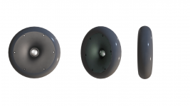
My current plan is to build a separate box for the midrange driver alone. This will be a highly profiled (rounded, beveled) box of approximately 12"H x 10"W x 9"D. Above this box will be a separate housing for the tweeter.
The tweeter housing will be cylindrical with radiused edges. The tweeter baffle will continue the profile of the waveguide all the way around to the back of the housing. The waveguide is about 6.75" diameter, and the housing will be 10" diameter, with a 1.5" radius. The cylinder housing will have a depth of about 3", and the rear will have a 1.5" radius as well.
The attached graphic is conceptual, it is not to scale. But it gives an illustration of what I am thinking at this point.
j.
My earlier sketches had the midrange and tweeter mounted in a single box. I simulated a variety of layouts, spacings, edge bevels/shapes. A lot of my better design concepts looked a lot like the March Audio Sointuva. This is a design which I have great respect for, but I did not really want to mimic this product so closely.
I am also influenced by the experimental work of @HeadShake with is naked floating tweeter. There is definitely something special about a tweeter with minimal baffle floating freely in space.
My current plan is to build a separate box for the midrange driver alone. This will be a highly profiled (rounded, beveled) box of approximately 12"H x 10"W x 9"D. Above this box will be a separate housing for the tweeter.
The tweeter housing will be cylindrical with radiused edges. The tweeter baffle will continue the profile of the waveguide all the way around to the back of the housing. The waveguide is about 6.75" diameter, and the housing will be 10" diameter, with a 1.5" radius. The cylinder housing will have a depth of about 3", and the rear will have a 1.5" radius as well.
The attached graphic is conceptual, it is not to scale. But it gives an illustration of what I am thinking at this point.
j.
Attachments
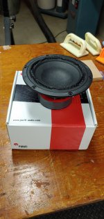
My Purifi PTT6.5M04-NFA-01 drivers arrived about a week ago. I am now finalizing the cabinet design.
My earlier sketches had the midrange and tweeter mounted in a single box. I simulated a variety of layouts, spacings, edge bevels/shapes. A lot of my better design concepts looked a lot like the March Audio Sointuva. This is a design which I have great respect for, but I did not really want to mimic this product so closely.
I am also influenced by the experimental work of @HeadShake with is naked floating tweeter. There is definitely something special about a tweeter with minimal baffle floating freely in space.
My current plan is to build a separate box for the midrange driver alone. This will be a highly profiled (rounded, beveled) box of approximately 12"H x 10"W x 9"D. Above this box will be a separate housing for the tweeter.
The tweeter housing will be cylindrical with radiused edges. The tweeter baffle will continue the profile of the waveguide all the way around to the back of the housing. The waveguide is about 6.75" diameter, and the housing will be 10" diameter, with a 1.5" radius. The cylinder housing will have a depth of about 3", and the rear will have a 1.5" radius as well.
The attached graphic is conceptual, it is not to scale. But it gives an illustration of what I am thinking at this point.
j.
The TW29BNWG has a hole at the back of the chamber. Not sure if it is just cosmetic or it opens into the cone. And not sure if a shallow housing will have any effect.
It's great, isn't it? I've never spent so little time developing the crossover. Everything just falls into place when the directivity and acoustic center of both drivers are the same.
I think this is the true value of waveguides in commercial products. Allows the use of a simple (cheap to produce) tweeter, a plastic waveguide (cheap to mass produce) and far less crossover parts (cheaper BOM)
When you cut costs you improve profits or lower the cost to the consumer. Win-win.
The only thing better is a coaxial IMHO.
I opened a Kali IN-8 V2, which at $399 is a bit of a bargain. And was shocked to see about $50 of parts in it.
Good luck building any a 3 way with DSP amd amps and cabinets for $400.
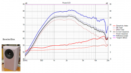
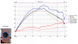
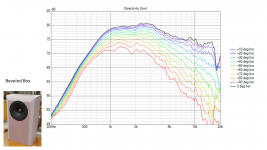
I wanted to see how much effect a beveled/radiused baffle had on the performance of this waveguide tweeter. So I constructed a flat panel baffle with a sharp square edge. The baffle was 10 7/8” x 15 ½” (275mm x 395mm). The driver was recessed flush with the surface, just as in the beveled box.
I was a bit surprised at how ragged and degraded the response became in this baffle. To see if I could improve the performance, I applied tape to smooth the small 1 mm discontinuity between the waveguide termination and the baffle. It helped a small amount, but not enough to be significant.
As you can see, the beveled box (described in post#2) has a significant performance advantage over the sharp edged baffle.
I have a few more prototypes to test before I settle on a final design for the tweeter baffle/housing. I am now considering a hexagonal shape. It might be easier to construct than a circular housing, given the tools and equipment I have. It may also be more aesthetically correct.
j.
Attachments
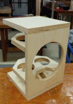
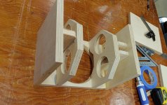
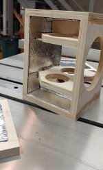
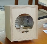
The midrange enclosure is designed. There is really not much complexity to it, given the size and the frequency range of the mid driver from approximately 200 - 2000 Hz. Since the design in complete, I decided to move forward with construction even though I have not finalized the design of the tweeter housing.
What I have shown in the pics is the inner carcass. I am using a lining of foil-backed butyl rubber damping. My last several projects have relied heavily on veneer for the cosmetics, and I am in the mood for something different. I am in the mood to work with solid wood again, so this project will be sheathed in solid wood. There will be an outer carcass of 3/4" cherry wood, and this layer will be beveled and contoured to minimize high frequency diffraction. I am looking forward to being able to shape and contour solid wood in a way that is not possible with a veneered surface.
What I have shown in the pics is the inner carcass. I am using a lining of foil-backed butyl rubber damping. My last several projects have relied heavily on veneer for the cosmetics, and I am in the mood for something different. I am in the mood to work with solid wood again, so this project will be sheathed in solid wood. There will be an outer carcass of 3/4" cherry wood, and this layer will be beveled and contoured to minimize high frequency diffraction. I am looking forward to being able to shape and contour solid wood in a way that is not possible with a veneered surface.
Attachments
You may want to increase your enclosure radius even more if you can. I used kerfed MDF and filled the slots with coarse fiberglass filler (aka kitty hair). The main offender with diffraction is the smaller radius based on my research. The golden ratio of enclosure dimensions may help further smooth FR out. Just a thought.
The midrange enclosure is designed. There is really not much complexity to it, given the size and the frequency range of the mid driver from approximately 200 - 2000 Hz. Since the design in complete, I decided to move forward with construction even though I have not finalized the design of the tweeter housing.
Do you really need that super-rigid box for midrange 200+ hz ?
good needlework 👍
- Home
- Loudspeakers
- Multi-Way
- Purifi + Waveguide Project