I am starting a new project, and as before, I am going to share my thoughts, results, successes, and failures, in the hope that others can benefit.
In my first speaker project, I established a basic architecture for a flexible 3-way system. A speaker stand with a Hypex 3 channel amplifier, a replaceable head unit containing the midrange and tweeter, and a separate bass box. https://www.diyaudio.com/community/threads/new-active-3-way-hypex-and-sb.352767/ My first system used good quality drivers, but I fully expected it to be a learning experience. I was pleasantly surprised at how good it sounded.
My second project (TXT) was a new head unit using much higher quality drivers. https://www.diyaudio.com/community/threads/new-active-satori-textreme.366347/ I incorporated improved cabinet construction techniques, including a butyl-aluminum damping layer on the interior. I was extremely pleased with the overall performance of the system.
My third project (Twin-8) https://www.diyaudio.com/community/threads/new-project-tower-3-way-with-twin-8s.378223/ was intended to address several questions/needs I had: (1) I wanted to design a speaker which had good Power and DI performance from the outset, using VituixCad to fully simulate and optimize the response. (2) I wanted a self-contained speaker which would be portable, and serve as a backup to my main system.
After comparing the Twin-8 to the TXT, I did some further refinement of the TXT DSP filter, and I was able to optimize the DI and Predicted In-Room response of the TXT system.
At this point I have learned many things about how my ear/brain perceives thing in my room. One thing I have learned is that good DI, ER, and PIR response is important up to a point. Once some level of smoothness is achieved, once it is within +/- 2 dB or so of some target response, additional improvements do not mean much. Another thing I learned is that high CtC spacing of 1.2x wavelength works well in practice, even though it looks weird. I learned that there are subjective differences in drivers, and once two systems are optimized to a highly refined level, the differences in drivers starts to have significance. I learned that with flat-baffle-mounted tweeters, it is possible to achieve acceptable DI and PIR performance, but it is not easy.
I am very curious about the extremely low distortion drivers from Purifi. The Purifi PTT6.5M has at least 10 dB lower IM distortion than other high end midrange drivers such as the ScanSpeak 12MU Illuminator, Satori MR16P, or Eighteen Sounds 6ND430. I am very curious to how this Purifi driver performs, objectively and subjectively.
===== ======= ====== ======
Index to this thread
Design constraints for this project post #280
https://www.diyaudio.com/community/threads/purifi-waveguide-project.394174/post-7359847
Conventional cabinet prototype (Bevel box) post #2
Early filter simulation post #31
https://www.diyaudio.com/community/threads/purifi-waveguide-project.394174/post-7233464
Free standing waveguide prototype (Foam donut) post #33, #44, #65, #106
https://www.diyaudio.com/community/threads/purifi-waveguide-project.394174/post-7260700
https://www.diyaudio.com/community/threads/purifi-waveguide-project.394174/post-7286772
Mid box construction post #38, #160, #175, #177
https://www.diyaudio.com/community/threads/purifi-waveguide-project.394174/post-7278809
https://www.diyaudio.com/community/threads/purifi-waveguide-project.394174/post-7318402
Modifying free standing waveguide prototype with sharp rear termination post #106, #111,
https://www.diyaudio.com/community/threads/purifi-waveguide-project.394174/post-7294235
Selecting free standing waveguide concept post #171
https://www.diyaudio.com/community/threads/purifi-waveguide-project.394174/post-7316583
Waveguide construction post #176, #188, #194
https://www.diyaudio.com/community/threads/purifi-waveguide-project.394174/post-7318998
https://www.diyaudio.com/community/threads/purifi-waveguide-project.394174/post-7332329
https://www.diyaudio.com/community/threads/purifi-waveguide-project.394174/post-7333484
Driver measurements in final cabinet post #196
https://www.diyaudio.com/community/threads/purifi-waveguide-project.394174/post-7349489
Description of woofer system post #230
https://www.diyaudio.com/community/threads/purifi-waveguide-project.394174/post-7351827
Final construction photos post #262
https://www.diyaudio.com/community/threads/purifi-waveguide-project.394174/post-7357092
Measurements and listening evaluation, Round 1, post #292
https://www.diyaudio.com/community/threads/purifi-waveguide-project.394174/post-7382731
Last edited:

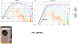
Before any preliminary simulation can begin, I need data to drive the simulation. With ordinary direct radiators, VituixCad provides a tool which uses an ideal piston model, and this is close enough to simulate an ordinary cone or dome driver. However, waveguides are different. I needed the waveguide tweeter to take some measurements to drive the simulation.
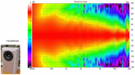
I chose the Satori TW29BNWG tweeter for this project. It has the same motor system as the TW29TXN-B (a driver I am so impressed with), and it has a beryllium diaphragm which I like. The waveguide seems intelligently thought out. It may not be the very best waveguide tweeter for a project like this, but it meets my needs and it is very convenient, pre-assembled, and readily available. The waveguide version of this tweeter is about $100 more than the standard flat-face TW29BN-B, and that seems reasonable for an aluminum waveguide.
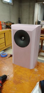
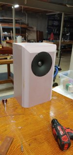
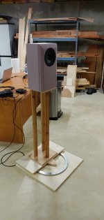
I made a prototype box from XPS foam to take horizontal polar measurements. The box matches my preliminary design dimensions for the new head unit. The bevel on the sides and top is a compound 30-60 degree bevel of 37 mm depth. This approximates a radius of 37 mm.
The response is very different from the flat face plate tweeters I have used in the past.
I chose the Satori TW29BNWG tweeter for this project. It has the same motor system as the TW29TXN-B (a driver I am so impressed with), and it has a beryllium diaphragm which I like. The waveguide seems intelligently thought out. It may not be the very best waveguide tweeter for a project like this, but it meets my needs and it is very convenient, pre-assembled, and readily available. The waveguide version of this tweeter is about $100 more than the standard flat-face TW29BN-B, and that seems reasonable for an aluminum waveguide.
I made a prototype box from XPS foam to take horizontal polar measurements. The box matches my preliminary design dimensions for the new head unit. The bevel on the sides and top is a compound 30-60 degree bevel of 37 mm depth. This approximates a radius of 37 mm.
The response is very different from the flat face plate tweeters I have used in the past.
Attachments
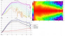
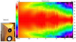
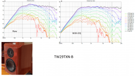
It is interesting to compare the response of this TW29BNWG to the tweeters in my other projects.
Waveguide dome tweeters need more EQ in the pass band than flat faceplate tweeters (typically), so to make a comparison that made sense to me, I used VituixCad to apply a simulated EQ to each tweeter to make it reasonably flat over the range from 1k to 20k… For me, this made it easier to compare.
It is clear to me that the directivity of the waveguide tweeter is very smooth. It very slowly and linearly increases in directivity from 1k to 10k. This should make the optimization of DI and Predicted In Room response significantly easier.
j.
Attachments


Nicely written. Some dumb questions - this XPS foam for prototyping, how does one cut the foam to flush mount a driver? Or is the front baffle not foam?
Re: 1.2 C-C wavelength -- what have your previous builds shown vs <1x, 1x, or other distances? It does look a bit weird on slide8.
Re: 1.2 C-C wavelength -- what have your previous builds shown vs <1x, 1x, or other distances? It does look a bit weird on slide8.
I wonder if that optimal center to center spacing would change with the Z-offset the waveguide provides the tweeter, in comparison to baffle flat mount.Another thing I learned is that high CtC spacing of 1.2x wavelength works well in practice
I use normal wood working tools... table saw, router, etc... The nice thing about Dow "Foamular" XPS board is that it cuts so fast and with so little effort. Power tools cut through it like a light saber... Very safe, almost no dust,this XPS foam for prototyping, how does one cut the foam to flush mount a driver? Or is the front baffle not foam?
Regarding the big CTC spacing... I got the idea from Kimmo. He wrote about it a year or so ago... If we can get the CTC down to 1/3 wavelength, then that is ideal... this is rarely possible. Simulations show that 0.5x to 1.0x are troublesome. 1.2x seems to work pretty good.
We discussed this quite a bit in this thread https://www.diyaudio.com/community/...3-way-with-twin-8s.378223/page-6#post-7017084
Since this will be an active speaker, I have the freedom to use DSP to EQ and delay the drivers. With passive crossovers of couse, the extra z-offset needs to be accounted for... I can imagine that in some cases the acoustic center of a waveguide tweeter would nearly match the woofer... maybe?I wonder if that optimal center to center spacing would change with the Z-offset the waveguide provides the tweeter, in comparison to baffle flat mount.
Awesome project.. 🙂 All the best 🙂
This is something I have been waiting for for some time now..
Though I feel there could be better waveguides out there, I would follow this project closely and wait for your subjective impressions especially about the tweeter performance.
Regards
Vineeth
This is something I have been waiting for for some time now..
Though I feel there could be better waveguides out there, I would follow this project closely and wait for your subjective impressions especially about the tweeter performance.
Regards
Vineeth
I thought about a Bliesma T34B in a waveguide... @augerpro has one, and there may be others... Still, I was apprehensive about doing surgery on a $500 driver. I have no capability for 3D printing, and working with a 3D print service starts to feel like work... My motto in retirement is "I do this for fun, if it aint fun, what's the point". I get great enjoyment out of the building process, and I like to build everything myself. If the time comes for me to make my own waveguide, I will be more likely to use a CNC router and mill it out of laminated hardwood. But that is a future project 🙂 I would need a CNC router first...
I used up my driver budget for this month when I bought the tweeters... the Purifi mids will have to wait till February... I also need to replace my 25 year old Delta surface planer.
j.
serious drivers budget.
I used up my driver budget for this month when I bought the tweeters... the Purifi mids will have to wait till February... I also need to replace my 25 year old Delta surface planer.
j.
Ahah...quite like your philosophy. Same here but plus I add for myself the snail factor.
That said, at this level I also assume personal preference play a role. The Be by SB Acoustics is loved by famous people. Not sure the Bielsma is better liked subjectivly.
Thanks Jim.
That said, at this level I also assume personal preference play a role. The Be by SB Acoustics is loved by famous people. Not sure the Bielsma is better liked subjectivly.
Thanks Jim.
It should be useful to compare the response you got replacing the box with a similar one without bevels. In my understanding a tweeter in a (well designed) waveguide should be pretty insensitive to baffle dimension/position.I made a prototype box from XPS foam to take horizontal polar measurements. The box matches my preliminary design dimensions for the new head unit. The bevel on the sides and top is a compound 30-60 degree bevel of 37 mm depth. This approximates a radius of 37 mm.
The response is very different from the flat face plate tweeters I have used in the past.
Ralf
I might tape some cardboard to the foamboard test box to simulate a hard corner. It would be interesting.It should be useful to compare the response you got replacing the box with a similar one without bevels. In my understanding a tweeter in a (well designed) waveguide should be pretty insensitive to baffle dimension/position.
I considered making measurements of the hard-cornered box before I cut the bevels. However, installing/removing drivers from the foamboard is a difficult process since the foamboard is delicate. The baffle can be worn out with as few as 4 or 5 installs. So to play it safe, I made the bevels first and then installed the driver.
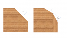
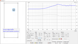
I intend this project to have generously profiled edges all the way around, front, back, sides, and top. I am motivated by the work of @Patrick Bateman and @mabat... they have shown that rounding and profiling the sides and back of a cabinet will have an effect... Mabat by simulation, and PatrickBateman by measurement. There results seem to apply to flat baffles, horns, and waveguides. My own experience has taught me that diffraction can have an impact that goes beyond the frequency response impact. High frequency diffraction (i.e. above the baffle step) in my opinion can be detrimental to the 3D illusion and sense of space, even when there is little measurable frequency response impact.
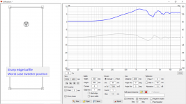
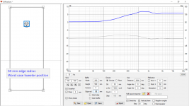
An example of what I mean: The first graphic shows a sharp edged baffle with tweeter in bad location. It is equidistant from both sides and the top. The second graphic shows what happens when a generous 50 mm radius is applied. Nearly all the high frequency diffraction effects are gone. The third graphic shows what happens if the tweeter is optimally located in a sharp edged baffle. Although it seems like the diffraction effects are greatly reduced, what has actually happened is that the diffraction peaks and nulls of the top, left side, and right side are balancing themselves out. Diffraction is still present, but when measured along this particular axis, the effect is masked. It is my opinion that we can hear a difference between the baffle of graphic 2 and the baffle of graphic 3.
j.
Attachments
My own experience has taught me that diffraction can have an impact that goes beyond the frequency response impact. High frequency diffraction (i.e. above the baffle step) in my opinion can be detrimental to the 3D illusion and sense of space, even when there is little measurable frequency response impact.
An example of what I mean: The first graphic shows a sharp edged baffle with tweeter in bad location. It is equidistant from both sides and the top. The second graphic shows what happens when a generous 50 mm radius is applied. Nearly all the high frequency diffraction effects are gone. The third graphic shows what happens if the tweeter is optimally located in a sharp edged baffle. Although it seems like the diffraction effects are greatly reduced, what has actually happened is that the diffraction peaks and nulls of the top, left side, and right side are balancing themselves out. Diffraction is still present, but when measured along this particular axis, the effect is masked. It is my opinion that we can hear a difference between the baffle of graphic 2 and the baffle of graphic 3.
j.
Agreed. In addition, When viewing what happens off axis; it is even more instructive.
The tweeter can be offset (often as little as 15-35mm or so) to give an acceptably flat and smooth response on axis.
But off axis from Hor 10 to Hor 90, it all gets a bit funky.
Virtually all of the top of the line speakers from the high end speaker manufacturers have been exploiting roundovers or facets for almost 50 years. From B&W (1979) to Peak Consult to Sonus Faber, all theirl top of the line products did not have a right angle.
I guess at that time it may have been a trade or industry secret. Not it’s clear that it’s an advantage. I don’t think they would go to the effort of extra work for nothing.
when one is taking one’s own measurements at 180 degrees (standing next to mic which is pointing at the back of the speaker); one can see that something like a sphere or droplet shaped is better, intuitively.
But it takes heroic efforts to build an enclosure like that.
The waveguide is the cheapest cheat to get a smooth response without a cabinet makeover- bring tweeter back along z axis (often helps time align the acoustic centre of tweeter to midrange), extends low frequency ability of tweeter compared to a flat face, and spares the tweeter from the diffraction effect of the right angle.
Last edited:
Yes... along with Avalon, Magico, Rockport, many others.Virtually all of the top of the line speakers from the high end speaker manufacturers have been exploiting roundovers or facets for almost 50 years. From B&W (1979) to Peak Consult to Sonus Faber, all theirl top of the line products did not have a right angle.
Please forgive my inexperience as I only understand next to nothing about fabrication.
Would anybody give me a list of PROGRAMS that are involved in the intricate painstaking artistic expression of such feats of everything involved. From crossover testing, or whichever to cad and sound analysis.
The masterpieces of life experiences are greatly admired.
Also, any lineage of similar evolution into certain classes would be lovely. For example, did dcm timeframes give influence on earlier times that evolved to George burn like Gods of speaker before me. In other words any stage progression and designs in the historical continuum of greats and influence on personal speaker designs would be adored. Thanks
- Home
- Loudspeakers
- Multi-Way
- Purifi + Waveguide Project