With the new data, the initial circuit seems quite good but IMO the most important part is the 500.5Hz pole (zero).
Disregard all previous recomendations.
As your real parts values are not exactly as Puresound schematic I suggest only:
R17 38K9 CADDOCK TF020R
Should be R17 = 38k9 // 2M62 = 38331r
C7 .006 paralleled .0022 = 8,2nF
Should be C7 = 6nF // 2.2nF // 0.1nF = 8.3nF
This way you preserve the 500.5 pole because 38331 x 0.0083 = 318.15 (almost 318)
I would also place a 7M paralelled to R1 but as SY noted, this is dependent of the tube used and also on the system... It should be ear tuned.
Lowering this R1 resistor (bypassing it with a larger one) produces a lift in the power zone.
Hi SY
Can Merlin use a lower resistor (to have less noise) ?
He also wants to use only 150v... what should he modify in the schematic ?
Can Merlin use a lower resistor (to have less noise) ?
He also wants to use only 150v... what should he modify in the schematic ?
It won't be less noise- the lower resistor also reduces gain. No free lunch.
One could design a preamp from scratch to run off 150V, but if you're going to build one that needs 240V, give it 240V. It's not like a raw supply is that difficult or expensive.
One could design a preamp from scratch to run off 150V, but if you're going to build one that needs 240V, give it 240V. It's not like a raw supply is that difficult or expensive.
Hi Merlin
If you must use 150v PSU, maybe you could build this one.
It is well tuned and very similar to the Puresound.
Anyway, if you choose to start from scratch, you must consider the Itch.
I heard fran´s unit and even in the internet it sounds wonderfull.
If you must use 150v PSU, maybe you could build this one.
It is well tuned and very similar to the Puresound.
Anyway, if you choose to start from scratch, you must consider the Itch.
I heard fran´s unit and even in the internet it sounds wonderfull.
Attachments
No load resistor = no sound. A regulator holds the voltage constant.
Sorry my ignorance load resistor = anode resistor?
Salas HV shunt reg can adjust also the current.
You are right without load resistor doesn't work.
I have tried with a 10K load resistor after the reg & still don't sound.
I have tried with a 10K load resistor after the reg & still don't sound.
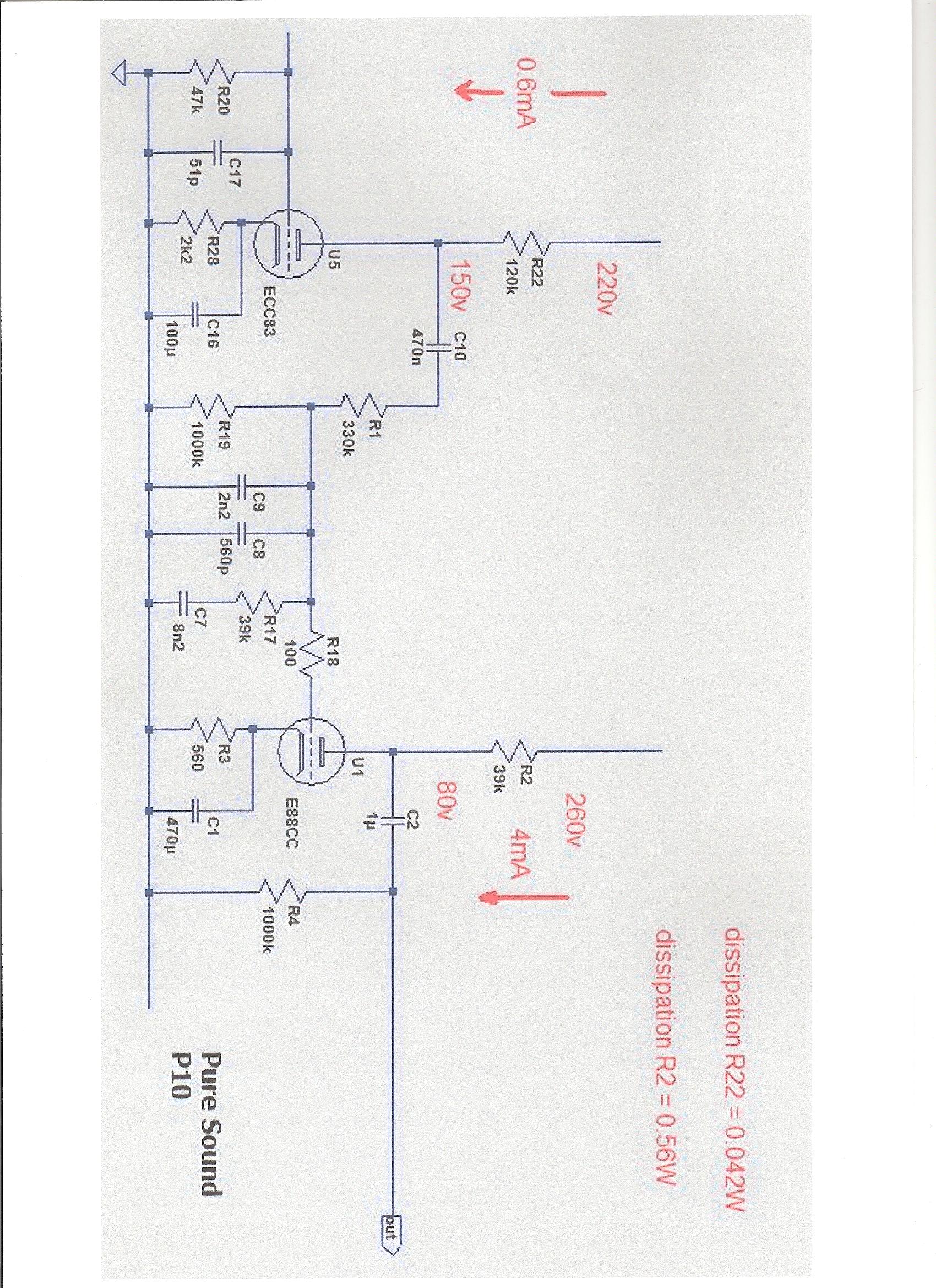
Hi MerlinJust received Guy answer:
"The internal resistance of an 83 is about 70Kohm which is in parallel with the 120K load resistor giving 44Kohm. This is added to the 330K and the result works in parallel with the 1M0 to ground giving 272K which is the net value used in the Eq calculation. The Miller capacitance of the 88 is 40pF which must be added to the 2n2 and 560pF to get the eq calculation spot on.
rgs
Guy"
Please forward my thanks to Guy
I used his input to finalize my riaa simulator.
Guy´s values confirm mine in all respects. 🙂
With the new data, the initial circuit seems quite good but IMO the most important part is the 500.5Hz pole (zero).
Disregard all previous recomendations.
As your real parts values are not exactly as Puresound schematic I suggest only:
R17 38K9 CADDOCK TF020R
Should be R17 = 38k9 // 2M62 = 38331r
C7 .006 paralleled .0022 = 8,2nF
Should be C7 = 6nF // 2.2nF // 0.1nF = 8.3nF
This way you preserve the 500.5 pole because 38331 x 0.0083 = 318.15 (almost 318)
I would also place a 7M paralelled to R1 but as SY noted, this is dependent of the tube used and also on the system... It should be ear tuned.
Lowering this R1 resistor (bypassing it with a larger one) produces a lift in the power zone.
Hi Merlin
Please forward my thanks to Guy
I used his input to finalize my riaa simulator.
Guy´s values confirm mine in all respects. 🙂
I forwarded your thanks to Mr. Guy, I'm a little bit confused:
C7 8.2nF or 8.3nF?
C8+C9 2.760pF or 2.2806pF or 2.986pF? (all + 40pF Miller)
R17 = 38k9 // 2M62 = 38331r
R1 = 329K // 1M optional fine ear tuned
C7 = 8.3nF
C8+C9 = 2.806nF
R17 = 38k9 // 2M62 = 38331r
R1 = 329k // 7M (Seven mega for optimal fine tuning)
C8+C9 = 2.806nF
R17 = 38k9 // 2M62 = 38331r
R1 = 329k // 7M (Seven mega for optimal fine tuning)
Last edited:
Did you decide about the PSU ?
For this design you should really use the 220v 260v otherwise you must recalculate R22 / R28 and R2 / R3 ratios.
These ratios work with the spec voltages and define the gain in both stages.
For this design you should really use the 220v 260v otherwise you must recalculate R22 / R28 and R2 / R3 ratios.
These ratios work with the spec voltages and define the gain in both stages.
I want to use the 10H 100mA choke for the PSU that I have, I asked Mr. Guy suitable mains transformer value in volts & amperes & suitable values for anode chokes instead the resistors.
PSU
I want to use the 10H 100mA choke for the PSU that I have, I need to know suitable mains transformer values in volts & amperes & suitable values for anode chokes instead the anode resistors without changing the cathode resistors.
I want to use the 10H 100mA choke for the PSU that I have, I need to know suitable mains transformer values in volts & amperes & suitable values for anode chokes instead the anode resistors without changing the cathode resistors.
But chokes have very low DC resistance... How do you plan to bias the triode ?
Maplin Valve Articles
Maplin Valve Articles
- Status
- Not open for further replies.
- Home
- Source & Line
- Analogue Source
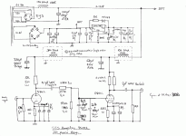
- Puresound P10 RIAA