believe me - that cap is beneficial only if smallest one is used
ceramic is perfect , but use whatever you have in drawer
as I said - start from 1nF upwards
regarding visit to Italia .......... who knows ...... all roads are heading to Rome , anyway
ceramic is perfect , but use whatever you have in drawer
as I said - start from 1nF upwards
regarding visit to Italia .......... who knows ...... all roads are heading to Rome , anyway
believe me - that cap is beneficial only if smallest one is used
ceramic is perfect , but use whatever you have in drawer
as I said - start from 1nF upwards
regarding visit to Italia .......... who knows ...... all roads are heading to Rome , anyway
Ok tomorrow it will be the first thing I do.
I recently live near Milano,so you should consider the idea to visit the next TOP AUDIO nex September.
But this is an other story😀
Thanks and good night!
Last edited:
Hello Alex! the stuff may you seem strange, but I tried using a 4.7 nF
and I got a result slightly inferior that obtained with 1uF.
Logically, I carried out an analysis of all the frequency range Hz kHz MHz and found that in the range of kHz 1uF gives better results than 4.7 nF.
So now i decided to leave 1uF.😱
Now i need a good layout cables assembly.
Please can you give me same good link or informations, if you prefer, also in Private Post.
Thanks
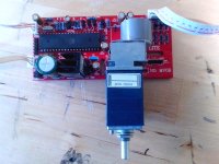
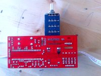
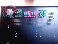
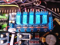
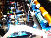
Hi Alex i will use the input selector and volume control showed in pictures attached (red pcb).
I had to change a few things to be able to make it suitable for balanced use . I also have replaced its original pot with a four-way 10K Alps (much better than the original).
In this way i will get the same functionality of the input selector shown in the last picture more the possibility of remote control.😉
In the third picture the last pcb on the right will serve to keep the outputs to ground for a few seconds (about 10) to avoid bump input to the power amp.
What do you think of this device?
Attachments
Last edited:
having daisy chain of pcbs .......... make it in simplest way , but be avare that you must use one central gnd point (per channel) - either output side of Shunty , or input side of Pumpkin
Halo ZM,
I'm still have problem with 1 channel. I can't set output offset for - Out (-25V). + Out have no problem (5mV).
I measure VGS for Q5 2.7V, VGS Q6 9.3V.
My supply +/-30V.
Didiet
I'm still have problem with 1 channel. I can't set output offset for - Out (-25V). + Out have no problem (5mV).
I measure VGS for Q5 2.7V, VGS Q6 9.3V.
My supply +/-30V.
Didiet
Last edited:
Hi Alex !I sent you in diy private mail a question about C5 aleph 30, please can you reply?
Thanks in advance
Antonio
Thanks in advance
Antonio
I did replied , but can't do again , because I deleted plenty of messages in my box
write here
write here
I did replied , but can't do again , because I deleted plenty of messages in my box
write here
The question is about C5 1nF Polyester (as project) or 1nF Silver Mica (can it be a upgrade) or without C5 (can the amp be yet stable or not),in this last case how i can check if it is yet in sure zone?
check for oscillations on output with CRO
if you don't have any , don't use these 1nF
if you need them - put whatever you have in drawer - no need for mica
if you don't have any , don't use these 1nF
if you need them - put whatever you have in drawer - no need for mica
check for oscillations on output with CRO
if you don't have any , don't use these 1nF
if you need them - put whatever you have in drawer - no need for mica
Sorry! What is CRO?😕
I need to use the oscilloscope and signal generator with 100hz 1khz and 10khz signal input?😕
COMPARE
the input signal to the output signal using a twin beam or dual trace Cathode Ray Oscilloscope (CRO).
Use a variety of signals, including sine, triangle and square, 10Hz to 50kHz, at a variety of levels.
"Compare" is the really important part of the technique.
the input signal to the output signal using a twin beam or dual trace Cathode Ray Oscilloscope (CRO).
Use a variety of signals, including sine, triangle and square, 10Hz to 50kHz, at a variety of levels.
"Compare" is the really important part of the technique.
Tony
for start - if you're not having enough praxis with CRO , just connect this (attached) across spk terminals,of course - with amp powered on
in silent , then with some light level muzak
if LED's are silent , you're good to go , without those two 1nF caps
for start - if you're not having enough praxis with CRO , just connect this (attached) across spk terminals,of course - with amp powered on
in silent , then with some light level muzak
if LED's are silent , you're good to go , without those two 1nF caps
Attachments
Cathode Ray Oscilloscope (CRO) ...Good to know,thanks Andrew!
About CRO use...i can try to find the power switch🙂 and after i can try also to do something more...but Alex i have to tell you ..."you know always something more of Devil" What mind had designed this circuit..almost doubt (for its simplicity) that will work!😀
Thanks Alex and Andrew!
About CRO use...i can try to find the power switch🙂 and after i can try also to do something more...but Alex i have to tell you ..."you know always something more of Devil" What mind had designed this circuit..almost doubt (for its simplicity) that will work!😀
Thanks Alex and Andrew!
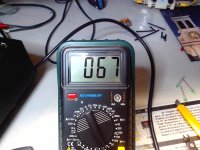
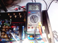
About shunty heatsink temperature
Hi at all! Please is normal about 70° measured on heatsink of shunty (no load connected and cover open ) ,or i have to add more alluminium sink?
Thank in advance
Antonio
Hi at all! Please is normal about 70° measured on heatsink of shunty (no load connected and cover open ) ,or i have to add more alluminium sink?
Thank in advance
Antonio
Attachments

Last edited:
without load , everything is dissipated on Shunty itself
when you connect load , dissipation will go down ........
so , just relax 😉
when you connect load , dissipation will go down ........
so , just relax 😉
without load , everything is dissipated on Shunty itself
when you connect load , dissipation will go down ........
so , just relax 😉
Thanks Alex!
I supposed instead that connecting the load shunty would collapse!
Sorry my mistake

- Home
- Amplifiers
- Pass Labs
- Pumpkin preamp - ordered by Steen , official making thread