If components were removed, could a steel wool pad be used to scour the pcb and remove these splinters or are they smal traces
I had problems with my Shuntkys. Nothing could remove the solid copper shorts except a craft knife.
You will need to look at the boards under a powerful magnifying glass to see how poorly they have been produced.
The blue paint covers up most of the awful production.
You will need to look at the boards under a powerful magnifying glass to see how poorly they have been produced.
The blue paint covers up most of the awful production.
the short on r29 referred output to ground so DC value on this leg was 0.
When removed all out leg are at right 100K referred to ground.
Now that shorted was removed all four output cap shows wandering DC in the 0-50 mV range.
When removed all out leg are at right 100K referred to ground.
Now that shorted was removed all four output cap shows wandering DC in the 0-50 mV range.
little update:
removed rc feedback on + and - output and now C4- C5 4,7 uF exit cap node is 0,1 mV. Caps are OK.
So I suspect that this wandering DC showed with rc feeback on (0-50 mV ) is normal.
Any suggestions?
removed rc feedback on + and - output and now C4- C5 4,7 uF exit cap node is 0,1 mV. Caps are OK.
So I suspect that this wandering DC showed with rc feeback on (0-50 mV ) is normal.
Any suggestions?
What is Pumpkin?
Where is the schematic?
You are commenting on something that you know nothing about.
.....
Any suggestions?
click on Pumpie Cook Book part of my sig - download Cook Book , and look at last page
added 4 resistors per channel - McMilans and input ones
that will increase offset wandering
diff offset is always rock stable
Hi Zen Mod,
thank you !
Would to read your recent upgrade on cook book but it it impossible to download.
Ciao !
Anto
thank you !
Would to read your recent upgrade on cook book but it it impossible to download.
Ciao !
Anto
click on Pumpie Cook Book part of my sig - download Cook Book , and look at last page
added 4 resistors per channel - McMilans and input ones
that will increase offset wandering
diff offset is always rock stable
Can't open the link. What exactly did you change or add to?
Can't open the link. What exactly did you change or add to?
Problem solved. Was able to open the file now. Thank you.
Attachments
I'm having a different problem when trying to download pdfs from DIYaudio.
Open in a new tab works OK.
Open in a new window works OK.
Click to open and the message displayed is corrupted file. Not ok.
I thought this was a problem inside my PC.
Open in a new tab works OK.
Open in a new window works OK.
Click to open and the message displayed is corrupted file. Not ok.
I thought this was a problem inside my PC.
Anyone with one of these and an osilloscope.
Can you please put scope across output terminals and record your results.
My two have 50mV 20MHz sine wave imposed on output with inputs short circuit.
All components are the correct values, everything is inserted correctly, component matching was by ZenMod himself. Two of them would tend to rule out component failure. THEY WORK but they oscillate horribly.
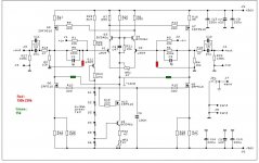
in case that you're going to alter gain , you need to increase C1 and C2 in same amount you decrease R5 and R6 ; their F0 needs to be in 250-300KHz
for decreasing gain is wise to somewhat increase R1 and R3 ( say to 22-27K) and then to decrease R5 and R6 to needed value
for decreasing gain is wise to somewhat increase R1 and R3 ( say to 22-27K) and then to decrease R5 and R6 to needed value
in case that you're going to alter gain , you need to increase C1 and C2 in same amount you decrease R5 and R6 ; their F0 needs to be in 250-300KHz
for decreasing gain is wise to somewhat increase R1 and R3 ( say to 22-27K) and then to decrease R5 and R6 to needed value
I'm not worried about frequency response at the moment, I'm just vtrying to stop these things oscillating.
what you think that role of that RC combo is ?
search for lag compensation or lag comp. capacitor
search for lag compensation or lag comp. capacitor
A perfect 20MHz oscillator.
Give me a break here, you designed the things and they dont work.
I'm not a designer.
One is exactly as you designed 10 X gain - It oscillates at 20MHz
One has be reduced to 2.7X gain = It oscillates at 20MHz
There are no exrernal influences - WHAT IS WRONG.
Everything is as according to your BOM.
It makes no odds whether it it is driven by Shuntky, simple regulator or no regulator, Pumpkin is a simple oscillator.
Last edited:
- Home
- Amplifiers
- Pass Labs
- Pumpkin preamp - ordered by Steen , official making thread